48
EN
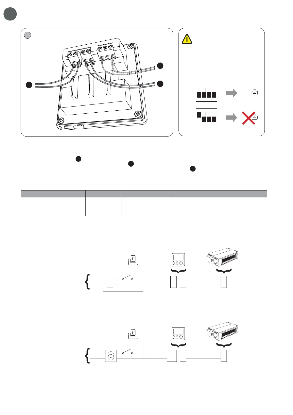
Cable connections must be made by tightening the screw-type terminal using a suitable star screwdriver; The connections to
be made are as follow:
• Serial cable, indoor units (
A
): terminals H1 & H2;
• External contact connection cable with 5-24Vdc signal (
B
): GND and VCC terminals (connect voltage signal to VCC terminal);
• External contact connection cable with 100-240V 50/60Hz alternating voltage signal (
C
): terminals L & N;
The features of the serial connection cable to be used are as follows:
Type of cable Max length Diameter Notes
Standard 2-pole cable with
PVC sheath
(60227 IEC 52 / 60227 IEC 53)
250 metres
from 2x0.75 to
2x1.25mm
2
Serial communication cable
NOT supplied with the equipment
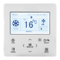
The wired Panel can manage two types of incoming signal from the control device: 100-240V
AC
(50/60Hz) or 5-24V
DC
Depending on the type of signal, the control device must be appropriately connected to the wired panel, as show in the following
layouts:
Connecting the wired panel to the external contact with 100-240V
AC
signal
N
L
N
L
H1
H2
H1
H2
100-240V~50/60Hz
Gate control
100-240 VAC
WRC1
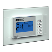
Connecting the wired panel to the external contact with 5-24V
DC
signal
H1
H2
H1
H2
100-240V~50/60Hz
Gate control
VCC
GND
5-24 VDC
WRC1
3
A
B
C
S1 DIP
S1 DIP
Gate control
Gate control
12
ON
34
12
ON
34
ON - ON
(default)
OFF - ON
The Gate Control function is ena-
bled by default; To disable, it is
necessary to act on the dip switch
S1 (placed on the electronic bo-
ard, and attainable by unscrewing
the 4 screws that close the plastic
shell), changing the dip 1 value,
as shown in the fi gure: