28
16 CALIBRATION OF CHECK AND SAFETY
PARAMETERS
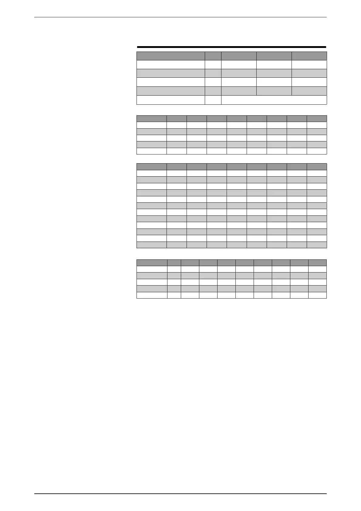
min. standard max.
Cooling set point °C 4 / -6
(1)
7 / -6
(1)
14
Heating set point °C 35 48 50
Antifreeze intervention °C
-9 3
4
Total differential °C
35
10
Autostart
auto
CHECK PARAMETERS
NOTE
(1) = version Y
161 THERMOMAGNETIC
SWITCHES
FANS
All units are thoroughly tested in the
factory before shipping. Nonetheless,
it is always good practice to check all
control and safety systems after a
reasonable period of operation.
All the control operations must be
carried out by qualified personnel; the
wrong settings on the above devices
can cause serious damage to the unit.
16.3.1 High pressure switch
The high pressure switch stops the
compressor (generating the relative
alarm) when the delivery pressure
exceeds the set value.
The control of its correct working can
be made by closing the air suction
on the exchanger (in cold mode) and,
keeping the high pressure gauge under
control, checking it intervenes upon
reaching the calibrated value.
WARNING
If the switch does not trip at the
calibrated value, stop the compressor
immediately and identify the cause.
Reset is manual and only enabled
once the pressure drops below the
differential value. (For the set and
differential values, see the technical
manual).
16.3.2 Low pressure switch
The low pressure switch stops the
compressor (generating the relative
alarm) when the suction pressure
drops below the set value. The control
of its correct working can be made
(after about 5 minutes of operation) by
slowly closing the tap on the liquid pipe
and, keeping the low pressure gauge
under control, checking it intervenes
upon reaching the calibrated value.
WARNING
If the switch does not trip at the
calibrated value, stop the compressor
immediately and identify the cause.
Reset is manual and only enabled
once the pressure rises above the
differential value. (For the set and
differential values, see the technical
manual).
16.1.3 Anti-freeze control
The anti-freeze control, managed by
electronic regulation and by
the temperature probe at the
evaporator outlet, has the job
of preventing the formation of
ice when the water flow rate
is too low. The control of its
correct working can be made
by gradually increasing the anti-
freeze set until it exceeds the
0800 0900 1000 1250 1400 1500 1650 1800
n° Ventilatori
MTV 1 17 A 17 A 9 A 9 A 13 A 13 A 13 A 17 A
MTV 2 17 A 17 A 9 A 9 A 13 A 13 A 13 A 17 A
MTV 3 / / 9 A 13 A 13 A 13 A 13 A 17 A
MTV 4 / / 9 A 13 A 13 A 13 A 13 A 17 A
0800 0900 1000 1250 1400 1500 1650 1800
MTC1 53 A 57 A 53 A 53 A 57 A 57 A 53 A 53 A
MTC1A 53 A 57 A 53 A 53 A 57 A 57 A 53 A 53 A
MTC1B 53 A 57 A / / / / 53 A 53 A
MTC2 57 A 57 A 53 A 53 A 57 A 53 A 53 A 57 A
MTC2A 57 A 57 A 53 A 53 A 57 A 53 A 53 A 57 A
MTC2B 57 A 57 A / / / 53 A 53 A 57 A
MTC3 / / 53 A 57 A 57 A 57 A 53 A 53 A
MTC3A / / 53 A 57 A 57 A 57 A 53 A 53 A
MTC3B / / / / / / 53 A 53 A
MTC4 / / 53 A 57 A 57 A 53 A 53 A 57 A
MTC4A / / 53 A 57 A 57 A 53 A 53 A 57 A
MTC4B / / / / / 53 A 53 A 57 A
16.2 THERMOMAGNETIC
SWITCHES
COMPRESSORS
16.3 TRANSDUCERS
PRESSURE SWITCHES
KEY
PA High pressure switch
PB Low pressure switch
TRA High pressure transducer
TRB Low pressure transducer
0800 0900 1000 1250 1400 1500 1650 1800
PA cold 27 27 27 27 27 27 27 27
PA hot H2727272727272727
PB HL22222222
TRA 27 27 27 27 27 27 27 27
TRB 11111111