34
INSTALLATION HYDRAULIC DIAGRAMS AND WATER FEATURES
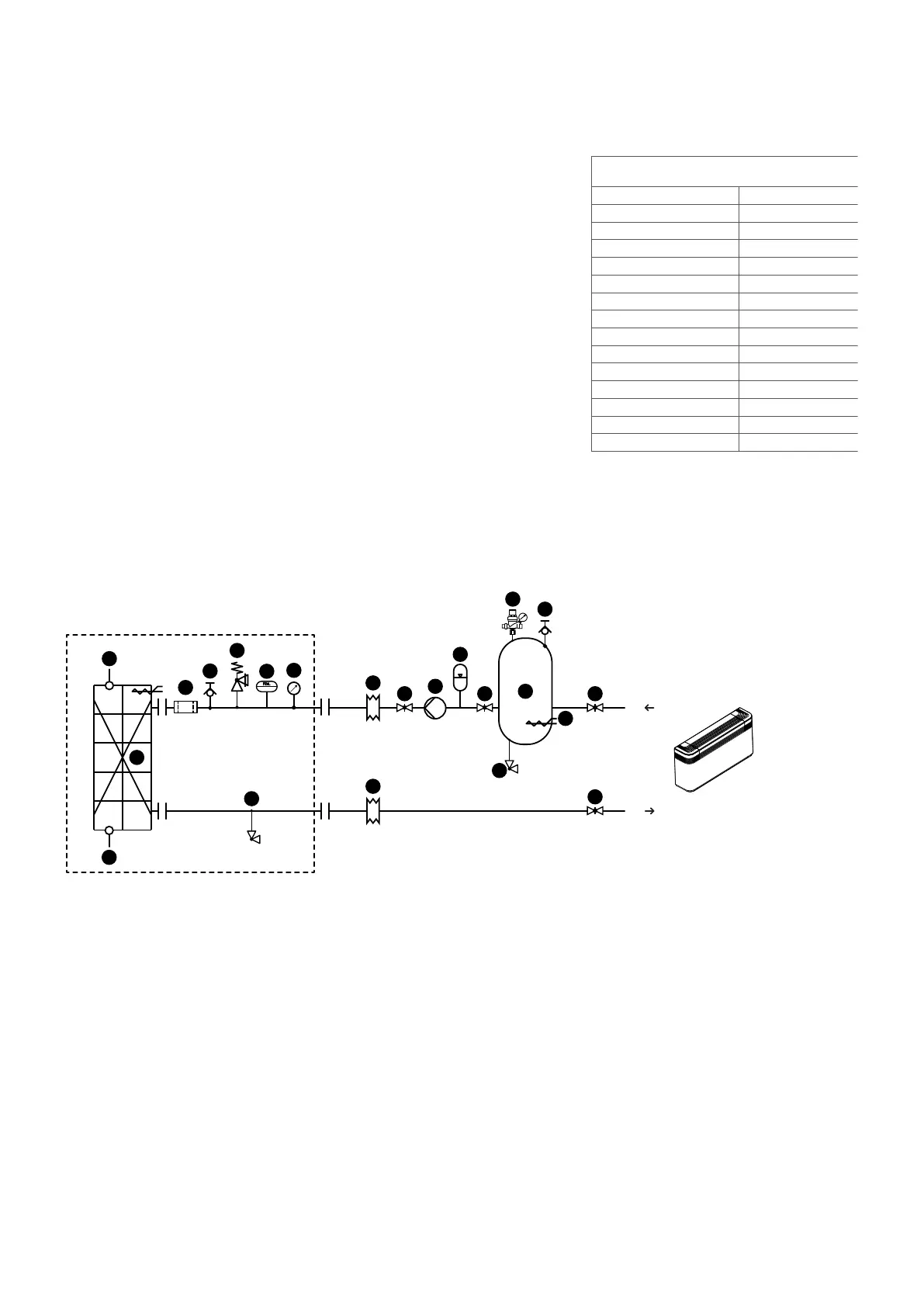
internal and external hydraulic circuit NRB 00 (standard)
Unit Components recommended
4
13
1
2
2
5
6
7
8
9
10
10
11
11
11
11
12
14
3
5
9
COMPONENTS PROVIDED AS STANDARD
1 Plate heat exchanger
2 Water temperature sensors
3 Antifreeze electric heater (standard in the heat exchanger)
4
Water lter
5
Air vent valve
6
Safety valve
7
Flow switch
8
Pressure gauges
9
Drain valve
HYDRAULIC COMPONENTS RECOMMENDED EXTERNAL TO UNIT
(RESPONSIBILITY OF THE INSTALLER)
3 Antifreeze electric heater
5
Air vent valve
9
Drain valve
10
Anti-vibration joints
11
Cut-o valve
12
Pump
13
Expansion Tank
14
System buer tank (installation recommended whenever the system water content is less than
that indicated in technical manual)
15
Automatic Filling Valve
water features
System: Chiller with plate heat exchanger
PH 7,5-9
Electric conductivity 100-500S/cm
Total hardness 4,5-8,5°dH
Temperature < 65°C
Oxygen content < 0,1 ppm
Max. glycol amount 50%
Phosphates (PO4) < 2ppm
Manganese (Mn) < 0,05 ppm
Iron (Fe) < 0,3 ppm
Alkalinity (HCO3) 70 - 300 ppm
Chloride ions (Cl-) < 50 ppm
Sulphate ions (SO4) < 50 ppm
Sulphide ion (S) none
Ammonium ions (NH4) none
Silica (SiO2) < 30ppm
 Loading...