47
J1.G0
J19.ID16H
J19.ID15H
J19.ID15
J19.IDC15
J19.ID16
J20.ID17
J20.ID18
J20.IDC17
J4.VG
J1.G
e J1.G
e J2.VG
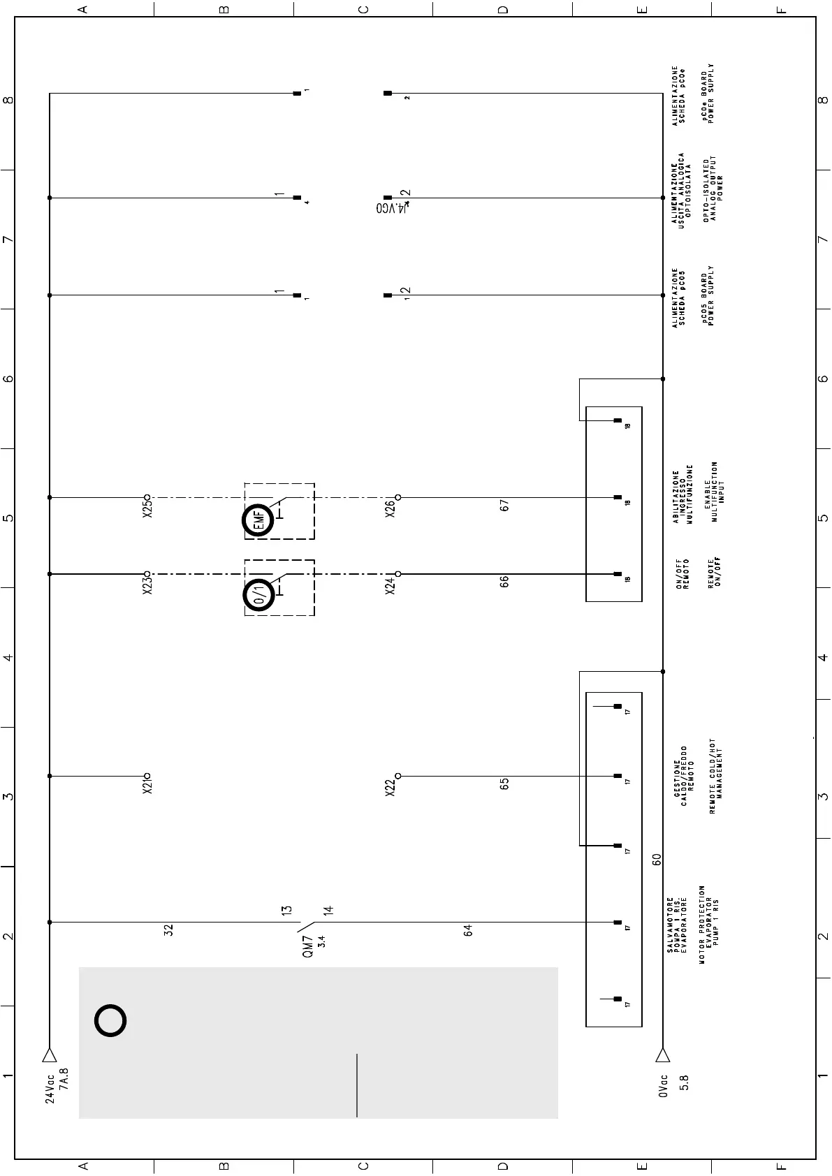
CONNECTING THE AUXILIARY CONTROL BOARD
Key:
the auxiliary control board points highlighted with a circle are
the ones that the installer can use.
0/1 remote ON/OFF
EMF Multi-purpose input (just the enabling)
• chiller power limiting
• setpoint (heating/cooling) variation
NB: for any other details, refer to
the complete electric diagram on
the machine.
 Loading...