40
g . 1
1
3
2
4
6
5
5
5
7
7
8
9
10
10
11
11
12
13
15
15
16
12
13
14
14
16
5
4
VARIABLE FLOW RATE SYSTEMS ON THE PRIMARY CIRCUIT WITH HYDRONIC KITS W1W2W3W4
Congurations W1-W2-W3-W4 are designed for single-ring systems with a
variable ow rate.
BENEFITS
This type of system produces:
• a simplied hydraulic circuit
• lower electricity consumption for pumping
WHAT THEY INVOLVE
These options include as standard: (g.1)
• Pumping units with high or low head, with the pumps driven by an
inverter
• Dierential pressure transducer and absolute pressure transducers:
pressure sensors for ensure ow rate modulation based on the
pressure dierence measured between two precise points indicated
on the hydraulic diagram
• Bypass branch with a motorised valve to ensure the minimum ow
rate required by the heat exchanger in all operating conditions
HOW THEY WORK
The system that this solution is applied to must have a certain number of
terminals with 2-way valves (On-O or Modulating) that vary the ow rate
during adjusted operation.
During the system design phase, make sure there are an adequate number
of terminals with 3-way valves (not subject to ow rate variation on the
supply), to guarantee the minimum ow rate on the circuit compatible
with the machine limits.
The system automatically modulates the number of pump rotations - and
therefore the water ow rate - on the basis of the pressure dierence
measured on the unit (and resulting from the opening or closure of the
2-way valves).
IT is essential to guarantee terminal regulation systems that, during
modulation, envisage an overall ow rate variation less than 10% per
minute of the current ow rate. (g.2)
Be sure to respect the minimum water content (refer to the “System water
content” chapter).
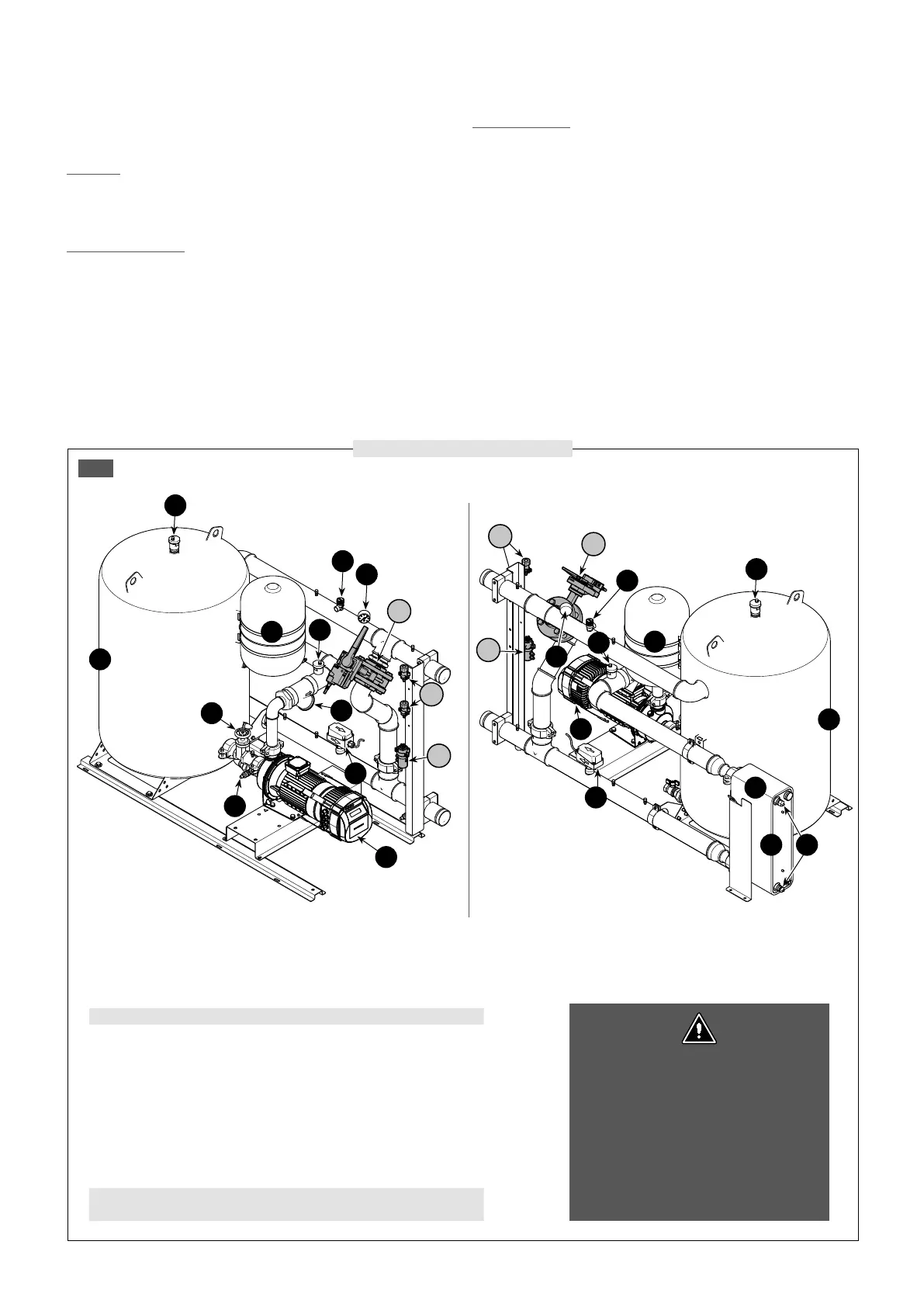
Hydraulic circuit con guration W3
The di erential pressure transducer (4) is
located on the rear of the unit, near the
two absolute pressure transducers (16), so
it can be accessed for maintenance. The
di erential pressure transducer (4) is the
starting point for the capillaries that are
then connected to the evaporator inlet
and outlet, as indicated in the hydraulic
diagrams on the following pages.
COMPONENTS PROVIDED AS STANDARD
1 Plate heat exchanger
2 Water temperature sensors
3 Antifreeze electric heater (standard in the heat exchanger and storage tank)
4 Di erential pressure transducer
5 Air vent valve
6 Water lter
7 Pump
8 Drain valve
9 Cut-o valve
10 System buer tank
11 Expansion Tank
12 Safety valve
13 Pressure gauges
14 Flow switch
15 Motorized by-pass valve
16 Pressure transducer
VARIABLE FLOW RATE SYSTEMS ON THE PRIMARY CIRCUIT WITH HYDRONIC KITS W1W2W3W4
 Loading...