41
g . 1
1
3
2
4
6
5
5
5
7
7
8
9
10
10
11
11
12
13
15
15
16
12
13
14
14
16
5
4
VARIABLE FLOW RATE SYSTEMS ON THE PRIMARY CIRCUIT WITH HYDRONIC KITS W1W2W3W4
Congurations W1-W2-W3-W4 are designed for single-ring systems with a
variable ow rate.
BENEFITS
This type of system produces:
• a simplied hydraulic circuit
• lower electricity consumption for pumping
WHAT THEY INVOLVE
These options include as standard: (g.1)
• Pumping units with high or low head, with the pumps driven by an
inverter
• Dierential pressure transducer and absolute pressure transducers:
pressure sensors for ensure ow rate modulation based on the
pressure dierence measured between two precise points indicated
on the hydraulic diagram
• Bypass branch with a motorised valve to ensure the minimum ow
rate required by the heat exchanger in all operating conditions
HOW THEY WORK
The system that this solution is applied to must have a certain number of
terminals with 2-way valves (On-O or Modulating) that vary the ow rate
during adjusted operation.
During the system design phase, make sure there are an adequate number
of terminals with 3-way valves (not subject to ow rate variation on the
supply), to guarantee the minimum ow rate on the circuit compatible
with the machine limits.
The system automatically modulates the number of pump rotations - and
therefore the water ow rate - on the basis of the pressure dierence
measured on the unit (and resulting from the opening or closure of the
2-way valves).
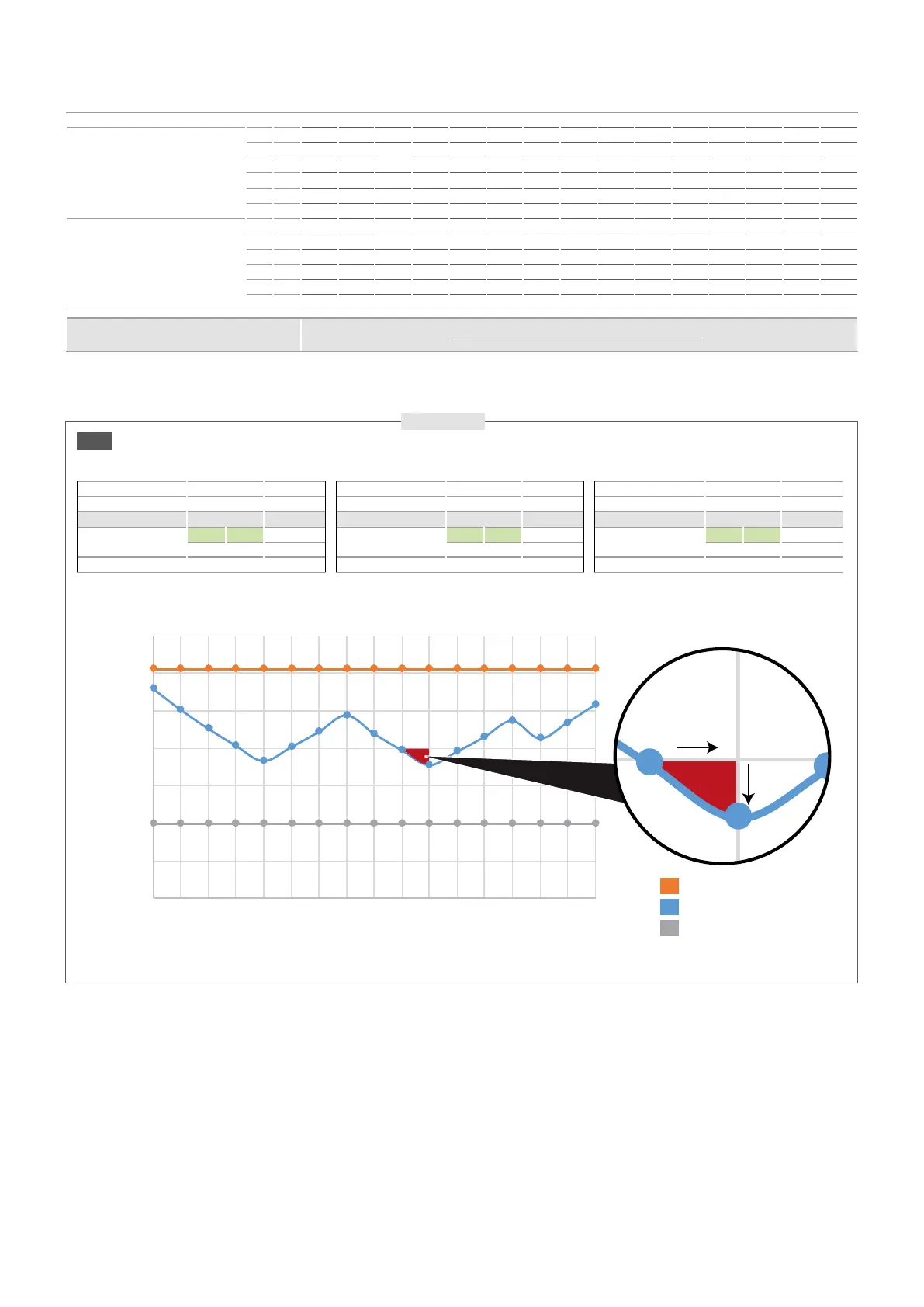
IT is essential to guarantee terminal regulation systems that, during
modulation, envisage an overall ow rate variation less than 10% per
minute of the current ow rate. (g.2)
Be sure to respect the minimum water content (refer to the “System water
content” chapter).
Hydraulic circuit con guration W3
The di erential pressure transducer (4) is
located on the rear of the unit, near the
two absolute pressure transducers (16), so
it can be accessed for maintenance. The
di erential pressure transducer (4) is the
starting point for the capillaries that are
then connected to the evaporator inlet
and outlet, as indicated in the hydraulic
diagrams on the following pages.
COMPONENTS PROVIDED AS STANDARD
1 Plate heat exchanger
2 Water temperature sensors
3 Antifreeze electric heater (standard in the heat exchanger and storage tank)
4 Di erential pressure transducer
5 Air vent valve
6 Water lter
7 Pump
8 Drain valve
9 Cut-o valve
10 System buer tank
11 Expansion Tank
12 Safety valve
13 Pressure gauges
14 Flow switch
15 Motorized by-pass valve
16 Pressure transducer
System side heat exchanger vers 0282 0302 0332 0352 0502 0552 0602 0652 0682 0702 0752 0604 0654 0704 0754
Min. ow rate
° l/h - - - - 8470 9222 10847 11635 13751 15403 16850 10810 12141 14693 16654
L l/h 4867 5545 6361 7367 8291 9004 10557 11296 13435 15005 16343 10469 11615 14322 16127
A l/h - - - - 8944 9882 11202 12058 14449 16086 17868 11172 12934 15215 17105
E l/h 5214 5887 6629 7686 8637 9510 10665 11403 13890 15324 16859 10526 12470 14475 16153
U l/h - - - 7973 8992 10086 11373 12638 14766 16473 18038 11871 13163 15533 17457
N l/h 5230 5942 6624 7722 8676 9673 11075 12240 14162 15928 17305 11489 12667 15015 16793
Max. ow rate
° l/h - - - - 24201 26348 30992 33242 39289 44008 48143 30885 34689 41979 47584
L l/h 13906 15843 18175 21049 23690 25725 30163 32275 38386 42871 46693 29910 33185 40921 46078
A l/h - - - - 25555 28234 32005 34451 41282 45959 51051 31920 36953 43472 48871
E l/h 14898 16820 18940 21960 24679 27171 30470 32581 39685 43783 48170 30074 35627 41357 46152
U l/h - - - 22779 25691 28817 32493 36107 42189 47065 51537 33916 37610 44381 49878
N l/h 14943 16978 18927 22063 24789 27639 31642 34973 40464 45509 49444 32826 36191 42901 47979
Permitted system ow rate variation
(options W1-W2-W3-W4)
Less than 10% per minute of the current ow rate *
NRB 0602 °
Min. ow rate 10847
Current ow rate (l/h) 12000 time: 3pm
Flow rate variation (l/h)
(- 10%) (+ 10%)
10800 13200 time: 3.01pm
Max. ow rate 30992
NRB 0602 °
Min. ow rate 10847
Current ow rate (l/h) 20000 time: 4pm
Flow rate variation (l/h)
(- 10%) (+ 10%)
18000 22000 time: 4.01pm
Max. ow rate 30992
NRB 0602 °
Min. ow rate 10847
Current ow rate (l/h) 30000 time: 5pm
Flow rate variation (l/h)
(- 10%) (+ 10%)
27000 33000 time: 5.01pm
Max. ow rate 30992
0 1 2 3 4 5 6 7 8 9 10 11 12 13 14 15 16
0
5000
0000
5000
0000
5000
0000
1 minuto
-10%
Water ow rate (l/h)
Minuts
Max. ow rate (l/h)
Current ow rate (l/h)
Min. ow rate (l/h)
g . 2
1 minute
* Example
 Loading...