32
INXWPY. 1610. 4438880_01
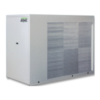
Key fig. 2
L1 Line 1
L2 Line 2
L3 Line 3
PE Earth
Fig.2
Fig.1
10.2. CONNECTION TO THE POWER SUPPLY
− Check there is no voltage on the electric line you want to use.
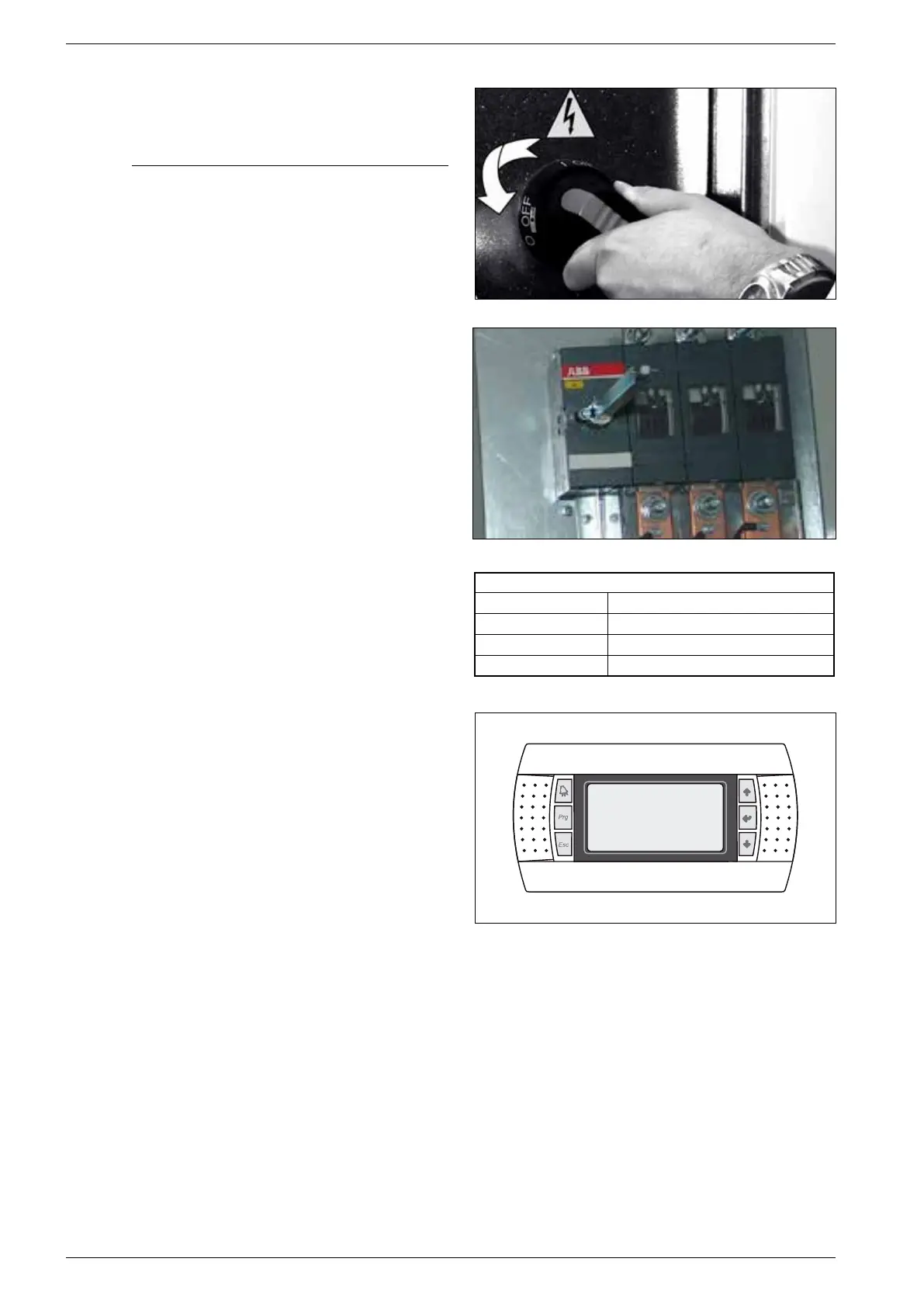
10.2.1. To access the electric box:
− Turn the electrical panel screws ¼ in counter-clockwise direction
− Turn the handle of the door-block disconnecting switch to OFF (see
figure). In this way, the electrical panel can be accessed
10.3. ELECTRICAL POWER CONNECTION
− For the functional connection of the unit, run the power supply
cable to the electrical panel inside the unit g. 1 and connect it to
the disconnecting switch terminals observing the phase and the
earth. g. 2
10.4. AUXILIARY CONNECTIONS AT THE USER/
INSTALLER EXPENSE
For installation requirements, refer to the wiring diagram supplied
with the unit. The wiring diagram together with the manuals must
be kept in good conditions and readily ACCESSIBLE FOR FUTURE
OPERATIONS ON THE UNIT.