P a g e | 3
Overview of System
Please read this entire manual before attempting to install this system.
This system should only be installed by a professional automatic gate installer or access control
specialist installer.
It is recommended that the system be range tested on site BEFORE being fully installed.
Site Survey
Before installing this system, you need to be sure that the range of the system will be sufficient.
The transmitter and speech unit can be powered up, call button pressed, and then check that the
handset will ring from all areas in which it will be used.
.
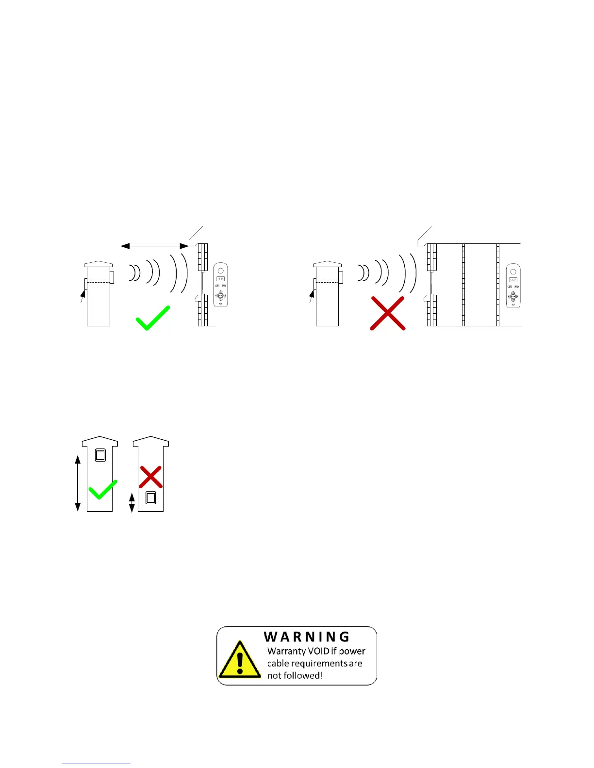
Tip: For longer range installations, locate the handset close to the front of the property, near a
window if possible. Concrete walls can reduce the open air range of 350 metres by 30-50% per
wall.
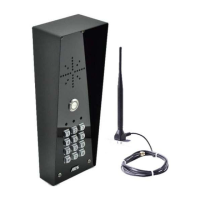
Mounting the Transmitter
Power Supply
TIP: Most technical calls received are due to installers using CAT5 or alarm cable to power
the unit. Neither are rated to carry enough power (1.2 amp peak). Please use following
cable…
Up to 2 metres (6 feet) – Use minimum 0.75mm
2
(18 gauge)
Up to 4 metres (12 feet) – Use minimum 1mm
2
(16 gauge)
Up to 8 metres (24 feet) – Use minimum 1.5mm
2
(14 gauge)
Using insufficient power cable thickness will cause excessive stress on electronic components,
and therefore void the manufacturer’s warranty.
The transmitter should be mounted as high as possible on the gate
pillar or wall to maximise range. Mounting close to the ground will
reduce range and is also more likely to be further restricted by long
wet grass, overhanging shrubs and vehicles.