P a g e | 6
Sense – N/C connected to (-)GND, to be connected to N/C door contact. Can be used to generate
door open or tamper alarm.
DU out – switches to (-) ground after the Duress Code is entered. Used to trigger alarm zone, or
buzzer to notify guard. 100mA sink, 24VDC.
K or A – Not used.
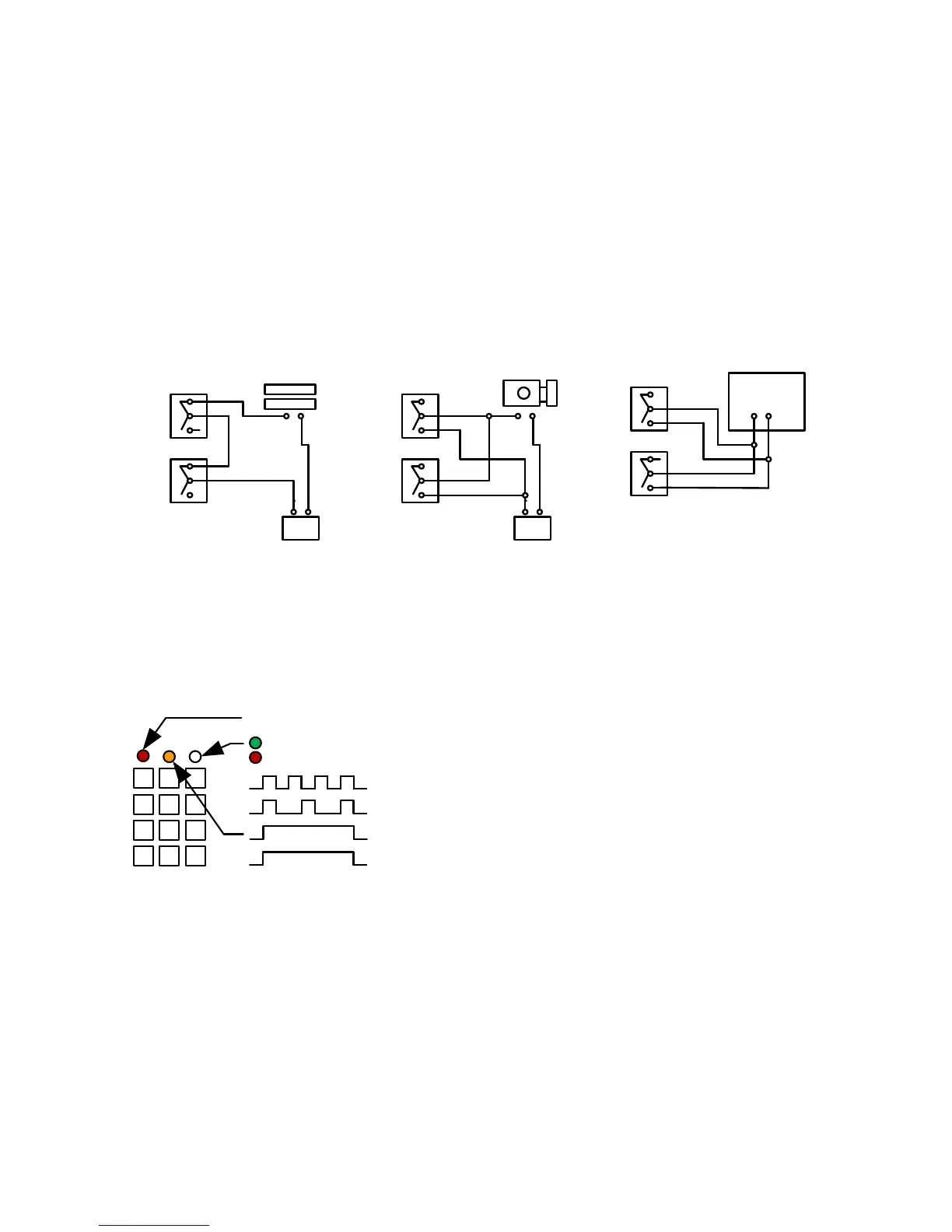
Wiring Tips
TIP: If your system has a keypad, it will need a relay connected to the lock or gate system as well
as the transmitter relay.
Connecting DC magnetic
lock
Transmitter
relay
Optional
keypad
output
Lock
Separate
PSU
Connecting AC/DC strike
lock
Transmitter
Relay
Optional
keypad
output
Lock
Separate
PSU
Connecting automatic gates
Start
Com
Gate controller
Transmitter
Relay
Optional
keypad
output
Keypad overview
This keypad has 3 outputs. The diagram below shows the LED indicators which indicate
programming and relay status information.
ON when incorrect codes entered and outputs are locked out.
1 2 3
4 5 6
7 8 9
* 0 #
SLOW FLASHING - in normal standby mode.
ON in programming mode.
ON when relay 3 activated.
GREEN when output 1 activated.
RED when output 2 activated.
FAST FLASHING – Wrong code entered / error.
TIP: After power up, as a security precaution, the keypad cannot be programmed for 60 seconds.
Once this time elapses, you may begin.
TIP: Flashing amber LED is normal standby mode!