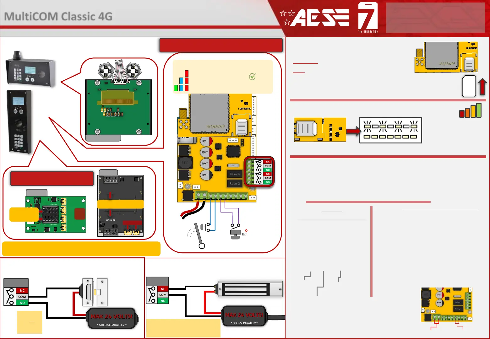
DETECT
Gate Position
Limit switch
(optional)
OPEN
Exit Button
(optional)
Relay 2
Relay 1
Wiring Connections
CHANGE APN (for VoLTE / 4G services)
Check with your network provider for the correct APN for 4G data.
Once you have confirmed the APN enter it in place of ‘APNinfo’ in an SMS to the intercom.
via SMS
(if connected to network)
1. Power off the unit, then short across the PB
terminals. (Hold the manager button if present)
2. Upon power up, a long tone will be emitted from
the speaker and the blue LED will remain solid - it is
now in the APN setting mode.
3. After this, enter the APN serial number through
the keypad then press #.
(e.g. if you want to set APN No. 18, press 1 - 8, then #.
A long beep will again be heard).
4. Reboot unit.
via Keypad (if no 3G signal)
Contact Technical Support or check our resource page
for a list of the APN serial number.
The system will be pre-programmed with the APN for the Vodafone network. If you wish to
use a different network then the correct APN must be set for full operation.
24v DC IN
PB Terminals
Ensure the PCB is powered on and connected
to the network with a GREEN flashing LED.
Then send the below text as an SMS to the
intercom Sim number. A power reboot is
required after the ‘OK’ reply message is
received back.
PCB Status LEDs
SOLID RED = PCB POWERED ON
SOLID RED +BLUE FLASHING = SEARCHING
SOLID RED + BLUE FLASHING + GREEN FLASHING = SUCCESSFULLY CONNECTED
Tip: All main connections are pre-wired. Below are
optional wiring additions for 3
rd
party controllers.
PROX PCB
AUXILIARY
CONNECTIONS
POWER
------------
COMMs
Tip: See the full manual for more
detail on auxiliary connections
9999#38#APNinfo#
Passcode
Command
(add APN)
APN info for
SIM network
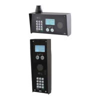
Prox and Keypad units are optional extra’s.
Up to 5 additional auxiliary Prox or Keypad units can be added to a single GSM PCB.
This will provide a maximum of 8 separate relays to control.
Keypad
ALTERNATIVE WIRING EXAMPLE
ALTERNATIVE WIRING EXAMPLE
Relay
STRIKE
LOCK
Relay
SECONDARY
MAGNETIC LOCK
LOCK POWER
SUPPLIES
ARE NOT
INCLUDED AS
PART OF THE
KIT.
These diagrams are provided for
guidance only. Please refer to the lock
wiring instructions before connecting.
2
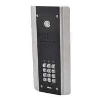
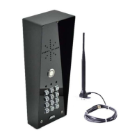
MultiCOM Classic 4G
- Advanced Multi-Resident GSM Intercom
* ALWAYS TEST THE UNIT ON SITE BEFORE INSTALLATION TO AVOID RE-STOCKING FEE * See full T&C’s on our website
STILL HAVING TROUBLE?
Find all of our support options such as Web Chat,
Full Manuals, Customer Helpline and more on
our website:
WWW.AESGLOBALUS.COM
SIM ORIENTATION
ALWAYS ensure the system is switched
OFF when adding or removing your
SIM card and ensure the orientation is
correct.
CONNECTION TO NETWORK
4G: Quick Flashing = Standby | Constant ON/OFF = Searching
MODEM LED
INDICATOR
SIM
 Loading...