The unit will not power up.
Check power supply voltage at intercom is 23.4v DC or more. Cable length from PSU to intercom
should be less than 25 feet and in 14 gauge for longer distances. See guide. Check the fuse.
The unit powers up but is not
showing network reception
or will not respond to SMS.
A. This means the unit is not able to detect the network for some reason.
-Power off the unit, remove the SIM and check it in a mobile phone to verify it can make a call and
has calling credit if it is a Pay As You Go SIM.
-
Disable any PIN code request if active on the SIM card.
Check the SIM is a standard voice capable SIM. If you are unsure, contact your SIM card provider
Check the reception is medium or good. Poor reception is not sufficient.
Power off, remove the SIM, use fine sand paper to lightly sand the SIM pads and contacts on the
GSM unit, lightly bend the contacts upwards so that they make better contact with the SIM and
try again.
-
Check antenna is connected and does not have too many sharp bends on the antenna cable.
Check the height of the antenna and make sure it is not inside a metal enclosure.
Check correct power cable size for cable length from PSU. Refer to manual for guidelines
Call is going to
voicemail if not
answered.
The unit calls the first
number, but voicemail comes
on before it can ring the
second number.
Decrease the calling time as per programming instructions.
The caller ID function
does not work.
Incorrect programming or
poor signal
If your number is a private or number withheld, then it will not work.
-
Ensure the number is programmed as you would normally dial it from another phone.
Ensure you have adequate GSM signal at the intercom by sending *20# as a text.
There is no audio from
the gate, but the
person at the gate can
hear ok.
This can be due to low
reception or excessively long
power cables or
Check reception level by *20#.
Change SIM card if necessary, to another network which may have better coverage.
Purchase a high gain antenna.
This may also be caused by a defective microphone, water on a microphone from a sprinkler for
example, or dirt/insects blocking the microphone hole. If reception is optimum and the problem
persists, contact your supplier or installer.
The audio quality that
can be heard on the
remote telephone is
poor or humming
(buzzing).
A small amount of GSM buzz can be considered normal on GSM intercoms, but not so much that
causes inability to hear the person speaking. This is a symptom of poor reception. Try above steps
on checking and improving reception. Consider fitting an external high gain antenna. Move the
antenna further away. Remove any short bends in the antenna. Ensure the spare antenna cable is
not rolled up inside the call station.
The trigger keys do not
work when the
intercom calls a phone.
Poor GSM signal at the gate
or issue with gate control
PCB
A. Check if you can hear the relay clicking at the gate when the keys are pressed during a call. If it
can be heard, then the system is working, check wiring between the relay and the lock or gate
panel. If the relays do not make a clicking sound, then check this feature on a different mobile cell
phone or landline. If it works on a different phone, check the settings on the phone in question
under DTMF tones.
Failure of DTMF tones to operate correctly is also a symptom of low reception or insufficient
power cabling. Check steps above on improving reception or addressing the power problem.
-
Also check that the relays are not already latched with the *22# command. If they are latched,
they need unlatched before the trigger keys will work.
-
Check if it works by SMS. Try latching a relay then use the status button to check if the relay is
latched. If that works, problem could be the phone being used, or low signal strength at the
intercom.
6
MultiCOM Classic 4G
- Advanced Multi-Resident GSM Intercom
* ALWAYS TEST THE UNIT ON SITE BEFORE INSTALLATION TO AVOID RE-STOCKING FEE * See full T&C’s on our website
STILL HAVING TROUBLE?
Find all of our support options such as Web Chat,
Full Manuals, Customer Helpline and more on
our website:
WWW.AESGLOBALUS.COM
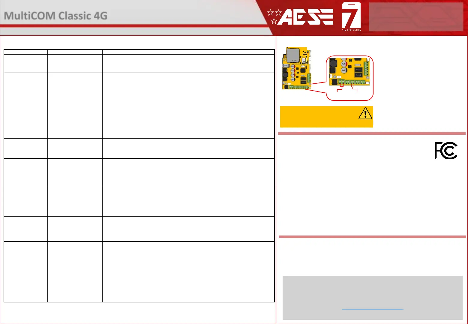
Reset / Default Unit
1) Power off the unit. (approx 60 secs)
2) Make a link across the terminals
marked OPEN.
3) Switch on power
4) After several seconds the relay will
click.
5) The unit will then clear memory and
be defaulted
6) Remove the link and wait around 20
seconds.
Note: Performing this process will
remove all current programming
including saved users & access codes.
This product is not a complete product until fully installed. It is therefore
considered a component part of an overall system. The installer is responsible to
check that the end installation complies with local regulatory requirements. This
equipment forms part of a “fixed installation”.
STILL HAVING TROUBLE?
Find all of our support options such as Web Chat, Full Manuals, Customer
Helpline and more on our website:
WWW.AESGLOBALUS.COM
+1 (321) 900 4599
24v DC IN
OPEN
Terminals
FCC Id: 2ALPX-PRIME6-XXXX-ZZ-4GA-YYY
(XXX = style & color, YYY is brand label, ZZ is mounting style)
Grantee: Advanced Electronic Solutions Global LLC
This device complies with Part 15 of FCC rules. Operation is subject to the following two conditions: (1) this
device may not cause harmful interference, and (2) this device must accept any interference received,
including interference that may cause undesired operation.
Output power listed is ERP below 1GHz for Part 22 and EIRP above 1GHz for Part 24. RF
exposure compliance is addressed for 1.1310 and 2.1091 MPE limits. The antenna(s) used
for this transmitter must be installed to provide a separation distance of at least 20 cm from
all persons.
End Users must be provided with transmitter operation conditions for satisfying RF exposure compliance.
 Loading...