32
17. Connect the free ends of the transmit and receive jumpers to the multimode link under test.
Clean jumper end that connects to patch panel prior to every test!
18. OPM will measure and display the insertion loss of the link under test.
19. Perform one of the following:
If using OPM4: Record link insertion loss at the current test wavelength.
If using OPM5: Press the Store key on the OPM5 to save the displayed measurement in the next
available memory location.
20. Repeat steps 17-19 for all links to be tested at the current wavelength.
Measure Multimode Link Insertion Loss.
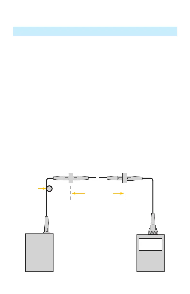
Step III - Measure Multimode Link Insertion Loss
Testing Multimode Links
OPM
OLS
2 dB
~
~
Link under test
Transmit jumper Receive jumper
Patch panelPatch panel
Mandrel wrap
 Loading...