34
10. Disconnect the transmit jumper from the OPM.
Do not disturb the transmit jumper at the OLS end!
11. If necessary, change the OPM adapter cap to match the connector on the receive jumper that will be
connected to the OPM.
Clean both ends of the receive jumper!
12. Connect the receive jumper to the OPM.
13. Mate the free ends of the transmit and receive jumpers using the appropriate adapter.
14. Verify that the insertion loss of this mated connector pair is under 0.75 dB, the maximum allowed by
the TIA (NOYES recommends 0.4 - 0.5 dB typical), as follows:
• Observe the displayed power level. This is the mated connector pair insertion loss of the test
jumpers in dB.
• If the insertion loss is not acceptable, disconnect the transmit and receive jumpers at the adapter,
clean the free ends of both test jumpers and repeat step 13 and 14.
• If the insertion loss is still not acceptable, replace test jumpers and repeat steps 1-14.
15. If the insertion loss is acceptable, disconnect the transmit and receive jumpers at the adapter.
16. Move the OPM and OLS to opposite ends of the link to be tested.
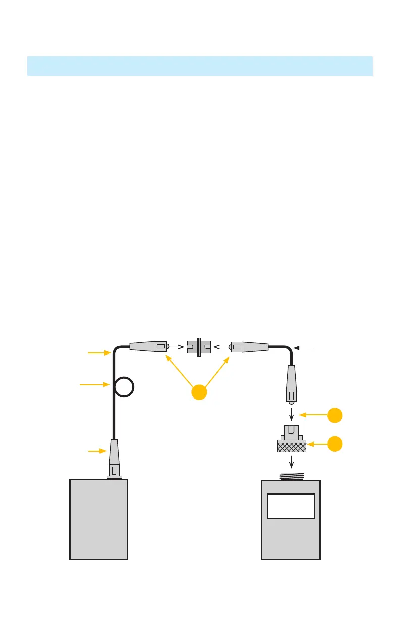
Verify Test Jumpers
Testing Single-mode Links
Step II - Verify Test Jumpers
OPM5
0.4 dB
OLS
New adapter cap
(if necessary)
Transmit jumper
Do NOT disturb
this connection
Receive jumper
13
12
11
30 mm loop
 Loading...