18
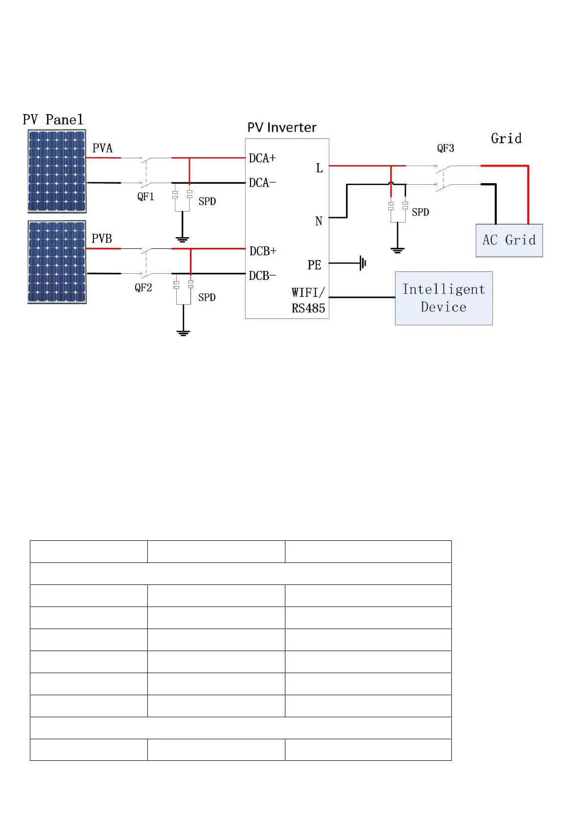
6 System Diagram
The typical connection diagram for the entire PV system is shown in the following figure.
1.PV array: Provide DC power to inverter
2. Inverters: Converts DC (Direct Current) power from PV panel(s) to AC (Alternating Current) power.
Because Inverter is grid-connected, it controls the current amplitude according to the PV Panel power
supply. Inverter always tries to convert the maximum power from the PV array.
3. DC Breaker: The current per DC string does not exceed 25A.
4. AC Breaker: Refer to the following table to choose the AC breaker.
Refer to the following table to choose the AC breaker.
Rate current of AC breaker[A]
Anyhome Series(Single MPPT tracker)
Anyhome Series(Double MPPT trackers)
Note:
QF1、QF2 : DC Breaker
QF3 : AC Breaker
SPD : Surge Protector