O r i g i n a l I n s t r u c t i o n M a n u a l f o r A F S A i r P u r i f i c a t i o n D e v i c e s
f o r R e m o v i n g O i l a n d E m u l s i o n M i s t
Produced By:
Neither transfer or reproduction of these documents nor application or disclosure
of their content are permitted without the explicit approval of AFS.
Violations will require compensation for damages.
Page 8 of 26
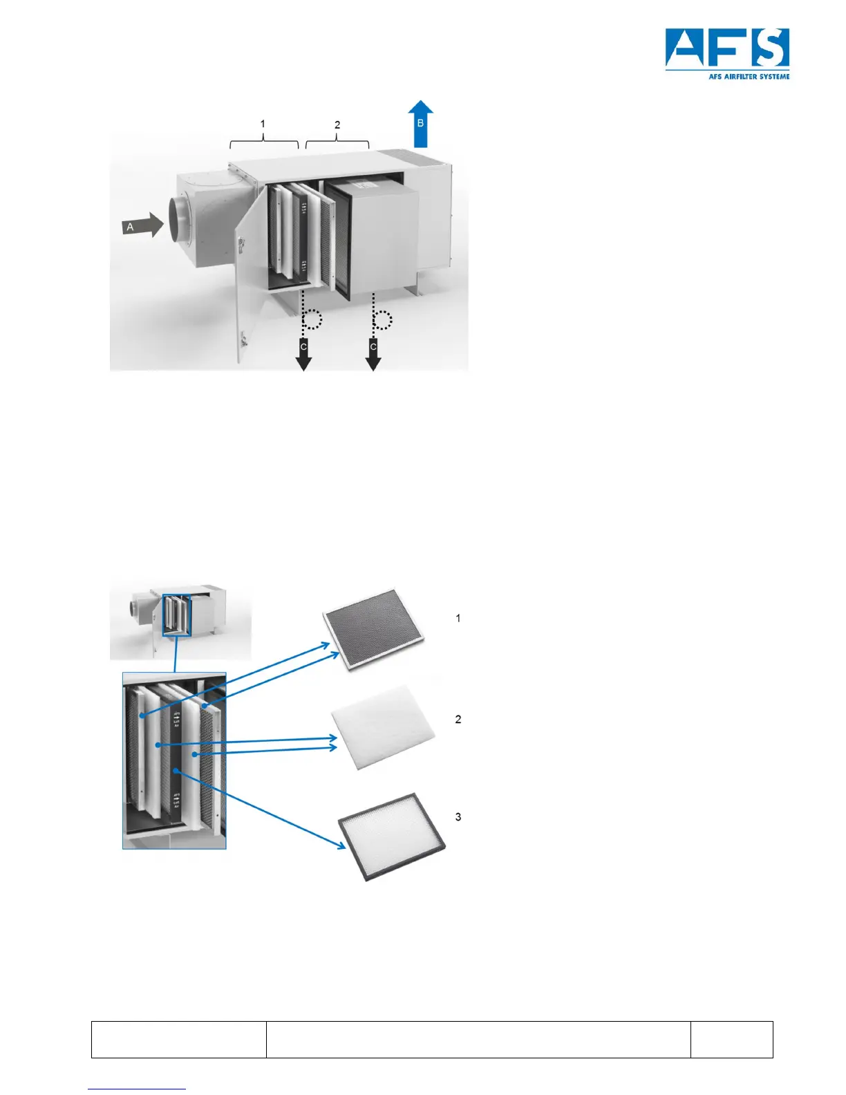
Figure 2: Exemplary description of material flows as well as separator and filter stages using the AFS 1600 as an
example
A polluted machine exhaust air
B purified exhaust air
C separated coolant lubricant/condensate
1 5-stage preliminary separation
2 Follow-up separator
Figure 3: Elements of the preliminary separation in AFS air purification devices
1 Metal mesh preliminary separator
2 Filter fleece (depicted without alternate frames)
3 Longlife separator