Neither transfer or reproduction of these documents nor application or disclosure
of their content are permitted without the explicit approval of AFS.
Violations will require compensation for damages.
Page 7 of 26
4 Design and function of the AFS air purification device
The operating principles and basic structure of all AFS air purification devices are the same; they differ
only in scale, ventilation system performance, airflow direction, number of filters used per cross-sectional
area (regardless of device type), color and layout of attachments.
4.1 Operating principle
Aerosols and particles from the coolant lubricant in the machine exhaust air are separated from/filtered out of
the air current in the AFS air purification device.
The separated coolant lubricant accumulates in the bottom area of the air purification device and drains
through the two siphon lines.
The suction output is generated by a motor fan wheel. The motor fan wheel is located in the airflow direction
after the post filter and thus on the clean gas side.
4.2 Design
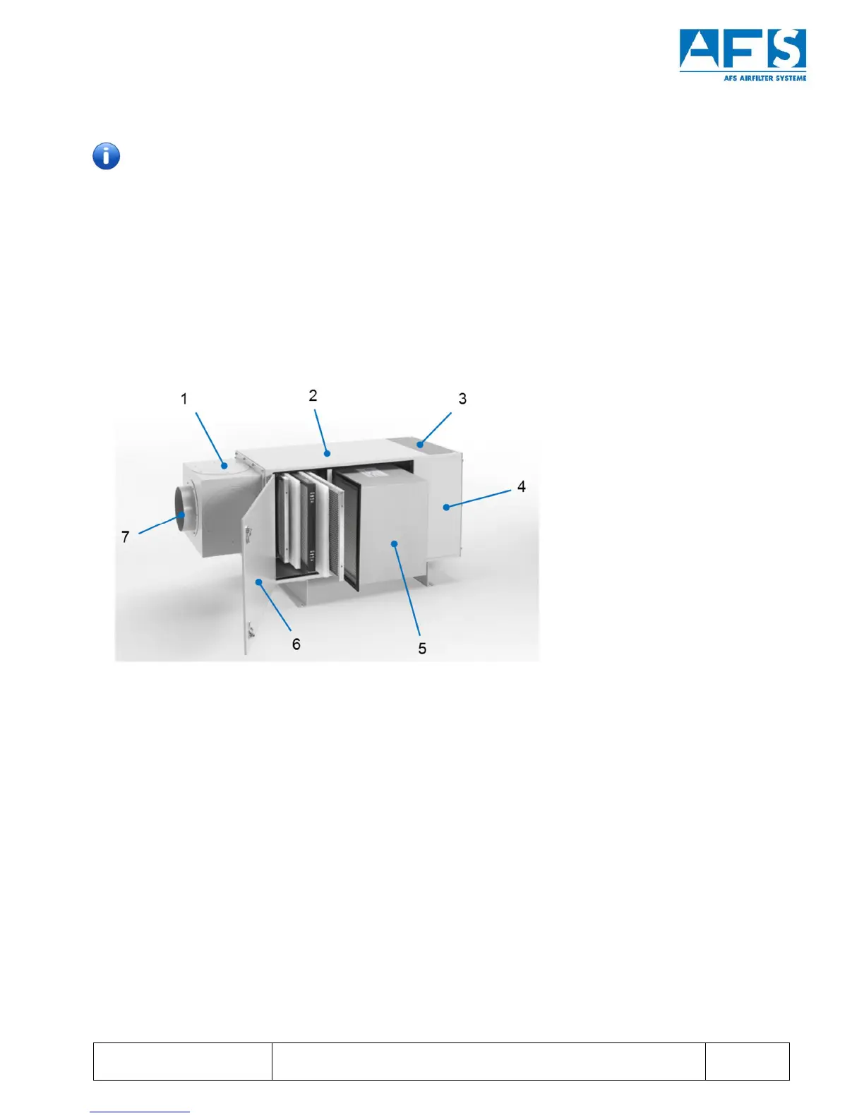
Figure 1: Exemplary design and component description using an AFS 100 with suction left as an example.
1 Suction on all sides of the device possible
2 Housing
3 Exhaust vent
4 Installation space for motor fan wheel
5 H13 filter or metal mesh follow-up separator
6 Maintenance opening (doors)
7 Hose or pipe connection