Installing the 2-way automatic/manual switch and potentiometer continues…
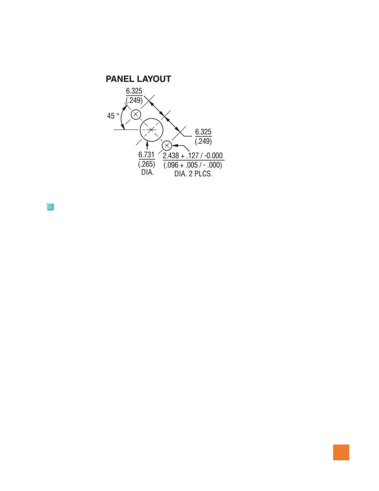
Figure 1.0.6 (Potentiometer panel layout – mm)
3.5 Installing the wiring Harness
*** Make sure that the battery is disconnected when installing the wiring harness of this system to
prevent any potential damage to any of the components.
1. Connect the main cannon plug of AC0188-A/B to the Granular controller AAP188.
2. Using a dedicated 10 A breaker, connect the (+) positive wire (12-28 VDC input) to the 10 Amp
breaker.
3. Connect the Ground wire to the (-) negative terminal of the battery or Ground bus terminal.
4. Route the wires for the Auto/Manual switch in the selected location and install.
5. Route the wires for the Potentiometer in the selected location and install.
6. Route the wire for the Left motor / encoder and connect to the Left motor.
7. Route the wire for the Right motor / encoder and connect to the Right motor.
8. Route the wire labeled “To Guia/Platinum com 4” from the Granular controller to the Guia
console harness labeled Com 3 & 4 port or the Guia Platinum harness labeled com 4.
See Figure 1.0.7 for more information on cabling.