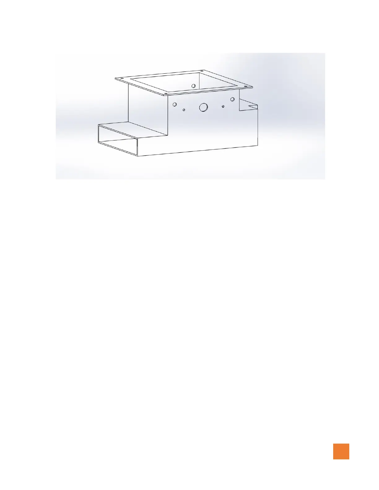
Figure 1.0.2 (4500 series broadcaster base after drilled-left side)
Installing the left/right motors with encoders continues…
6. Insert the left Granular housing into the left broadcaster and the right Granular housing to the
right broadcaster
7. Using the supplied M10 x 25 mm Socket Cap fasteners and M10 Lock washers, Insert these
through the drilled holes of the broadcaster into the Granular housing. There are 4 fasteners per
housing. Make sure not to overtighten these M10 Fasteners.
8. In some cases, to prevent granular material from falling between any gaps, a rubber, foam seal,
or silicone may be required to be installed around the gap of the granular housing and
broadcaster base to.
9. Using the supplied M5X 20mm sockets cap screws provided (2 per motor) install the left motor
with encoder to the left broadcaster and the right motor with encoder to the right broadcaster. See
diagrams (figure 1.0.3) below. Insure to not force but align the motor shaft into the brass fitting.
This step may require the impeller to be rotated until the flat surfaces are aligned.