19
Wiring external to the appliance must be installed in
accordance with the current National and Local Regulations
and Standards.
The cooker is supplied with a double insulated isolating
transformer, designed for 230v ~ 50Hz supply and protected
by a resettable fuse (resets within 2 minutes, after isolating
transformer from mains).
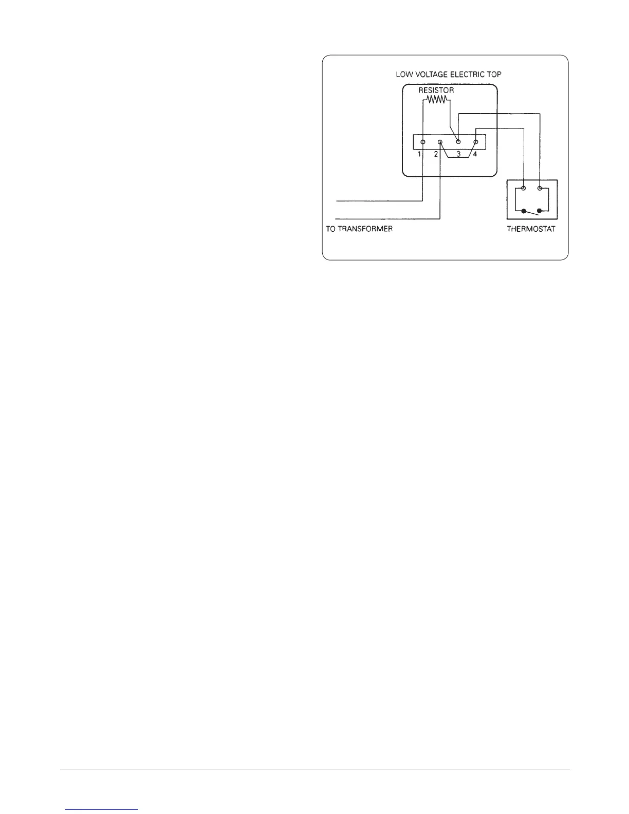
The transformer leads are connected to the low voltage
electric top mounted on the oil control valve top.
See Fig. 12.5 Wiring diagram of low voltage electric top.
The transformer can be plugged directly into an unswitched,
shuttered socket-outlet. The socket should be accessible and
adjacent to the appliance.
WARNING! The low voltage electric top must not be
connected directly to the mains supply.
ALWAYS use an AGA Transformer.
Tiling
Where the cooker is to stand in a recess or against a wall
which is to be tiled in no circumstances should the tiles
overlap the cooker top plate.
Flue chamber outlets
The cooker ue chamber can be converted to provide either a
horizontal or vertical ue outlet.
An extended horizontal ue connection is allowed upto
a maximum of 150mm in length when a back chimney
is constructed immediately behind the cooker (No bend
connections are allowed).
The vertical ue outlet is used for main ue connection via a
100mm diameter ue pipe between the ue chamber and
the chimney, etc.
Where the ue passes through a wall to reach a ue it must
rise at a minimum angle of 45°.
Fig. 12.5 Wiring diagram of low voltage electric top