20
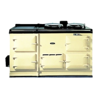
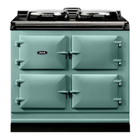
General installation of cooker
The complete cooker is oor mounted and the space in
which the appliance is to be tted must have the following
minimum dimensions:
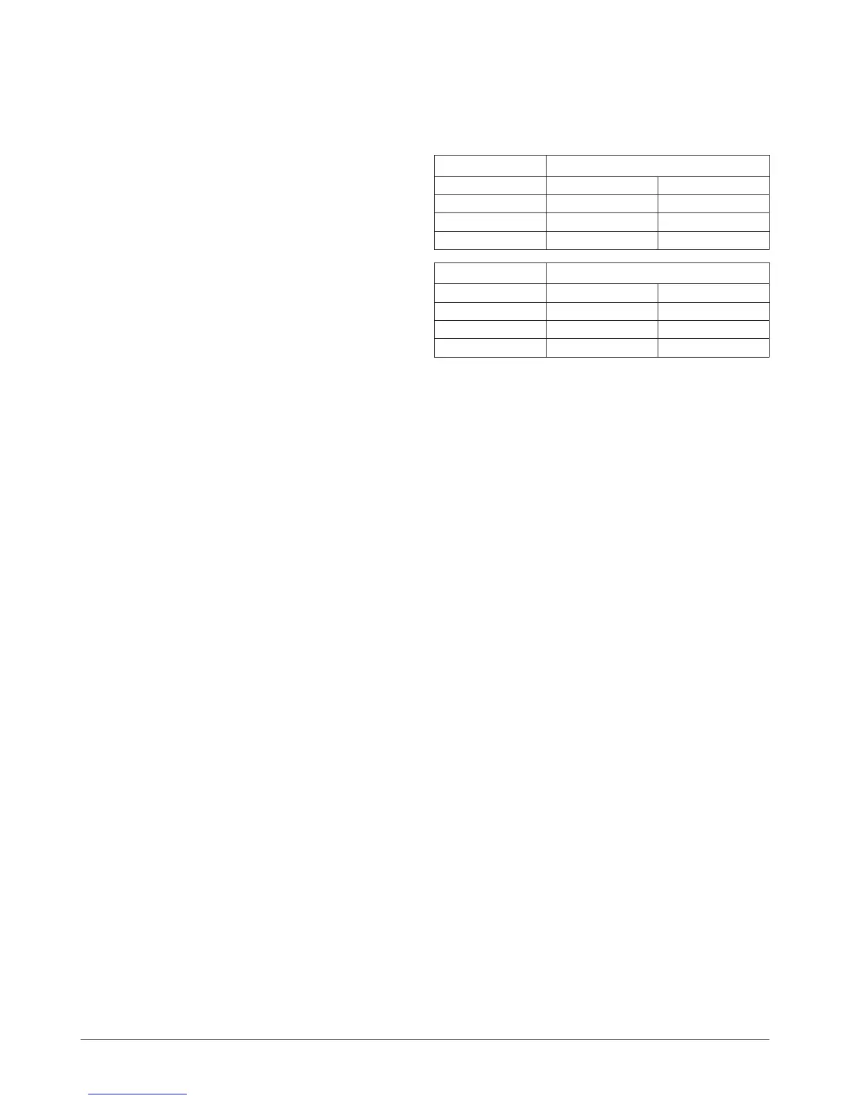
Oil valve left-hand side
Model OC OE
Width 1303 mm 1803 mm
*Depth 1130 mm 1130 mm
Height 1400 mm 1400 mm
Oil valve right-hand side
Model OC OE
Width 1187 mm 1687 mm
*Depth 1130 mm 1130 mm
Height 1400 mm 1400 mm
* Depth dimension includes door opening.
This space includes the following minimum clearances for
servicing:
Between wall and cooker side - 200mm adjacent to oil control
valve.
If the oil control valve is not tted against the cooker side
panels, then the width across a recess which does not
protrude beyond the front of the cooker may be reduced.
to:
• OC 1000mm
• OE 1500mm
A 3mm gap is required each side between the cooker top
plate and adjoining work surfaces that maybe tted. This is
to allow for the safe removal of the top plate should this be
required at a later date.
Above the raised insulating cover handle - 60mm.
To facilitate further oil servicing, a minimum clearance of
1000mm must be available at the front of the cooker.
Flue pipes and ttings must not be closer than 25mm
to combustible materials and where passing through a
combustible partition such as a ceiling or roof, must be
enclosed in a non-combustible sleeve providing a connector
space of at least 25mm.
Spacers around ue pipes passing through walls or oors
should be sealed against the passage of smoke and ame.
ASSEMBLE THE COOKER AS SEPARATELY INSTRUCTED
AND INSTALL/CONNECT THE OIL BURNER ELECTRICAL
SUPPLY.