21
Commissioning and lighting the burner
NOTE: BURNER BASE ENSURE THAT:
1. THE BASE IS LEVEL.
2. IT CONTAINS A 6MM DEPTH OF OIL.
3. THE BURNER SHELLS ARE SEATED PROPERLY
Lighting the Burner
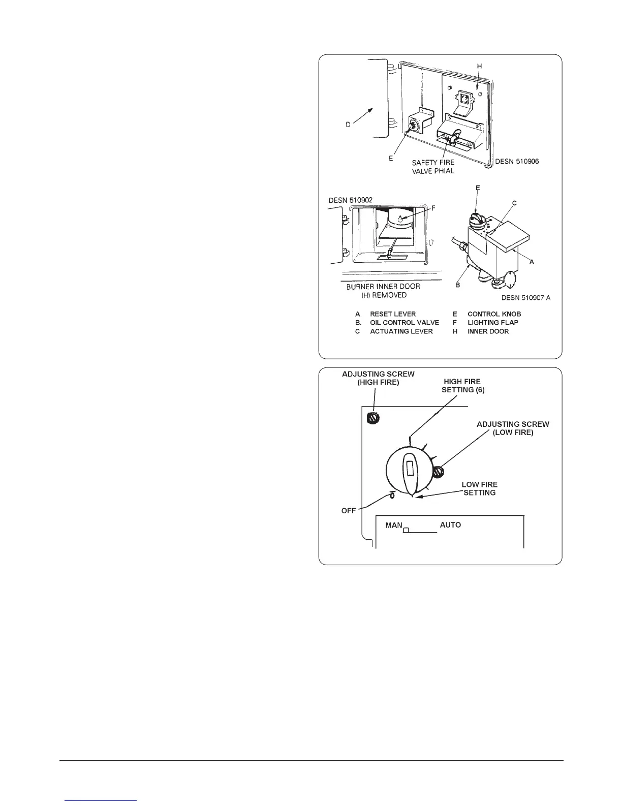
See Fig. 12.6 Wiring diagram of low voltage electric top
and Fig. 12.7 Control Knob and Man./AUTO Switch.
1. Ensure all oil valves are open and oil is in the oil control
valve. Turn control knob E to MK6 position.
2. Lift up the reset lever A on the front of the oil control
valve B.
NOTE: THE ACTUATING LEVER C ON THE ELECTRIC
TOP MOUNTED ON THE OIL CONTROL VALVE TOP
PERMITS MANUAL CONTROL TO OBTAIN MAXIMUM
OIL FLOW RATES IN THE EVENT OF POWER FAILURE
AND DEPRIVATION OF THERMOSTAT USE. ENGAGE THE
ACTUATING LEVER C BY PUSHING TO THE LEFT AND
ENGAGING IN THE NOTCH OF THE COVER.
THIS ALLOWS THE ACTUATING PLUNGER BUTTON TO
EXTEND UPWARD AND GIVE HIGH FIRE OIL RATE.
USE ACTUATING LEVER WITH POWER FAILURE ONLY.
3. Open outer burner door D, lift o inner door H and set
control thermostat knob E to Mark No. 6.
4. After allowing 15 minutes for oil to settle in the burner
base, lift the lighting ap F on the front of the outer
burner shell and light the front wick through the
lighting aperture.
5. Close the lighting ap F, ret inner door H, and close the
outer burner door D.
6. Connect transformer to mains supply.
7. The oil burner will gradually increase its oil rate, and
under the control of the thermostat, bring the complete
cooker up to temperature equilibrium, overnight.
Oil Rate and Combustion Checks
1. Remove the blanking plate and the oil lter within
the oil control valve and connect an oil ow gauge
assembly. The ow gauge must be capable of
measuring up to 10cc per minute.
2. With the burner alight at high re, check that the oil rate
corresponds with the rates given on Page 1.
3. After 30 minutes on high re, sample the ue products,
just below, but within the bottom of the ue chamber
with a Baccarach Smoke Pump. The Smoke Test should
indicate a Baccarach Smoke No. 0 - 1.
4. Disconnect the oil ow gauge and replace oil lter and
blanking plate in oil control valve.
Fig. 12.6 Wiring diagram of low voltage electric top
Fig. 12.7 Control Knob and Man./AUTO Switch