10
Remote Inhibit (INH) Circuit Testing
a. Turn on the 662x supply.
b. Momentarily short pins 3 and 4 of J702.
c. The front panel annunciator should indicate "RMT INHIBIT’’.
d. Turn off the 662x supply. This concludes testing of the INH circuit
Relay (RLY) Circuits Testing.
Using Method 1:
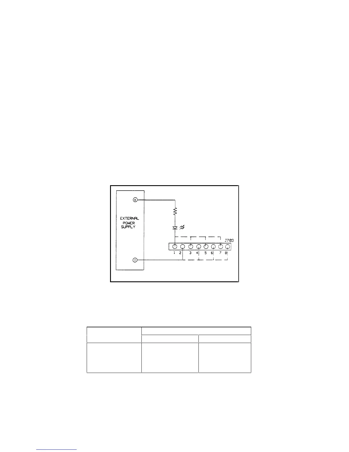
a. Connect the LED, resistor, and external 5Vpower supply to one set of relay output (RLY) pins on J703
(Refer to Table 2 and Figure 6b), and turn on the 662x power supply.
b. Send "RELAY <ch>, 0" to turn off the relay output under test.
c. The LED should be off.
d. Send "RELAY <ch>,1" to turn on the relay output (ch) under test.
e. The LED should be on.
f. Repeat steps a through e for each relay output < ch > .
Figure 6b. RLY Test Setup
Table 2. Relay Output Pins
Relay output J703 pins
<ch>
+-
112
234
356
478
 Loading...


