18 Verification
Table 2-4. Constant Voltage (CV) Tests (continued)
Action
Normal Result
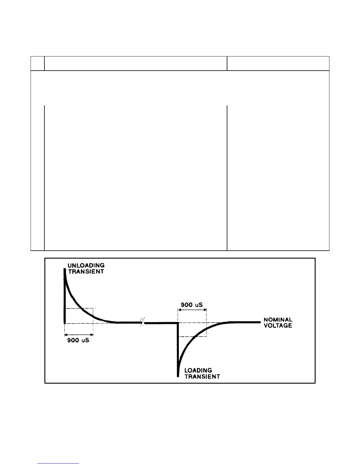
Transient Recovery Time
This test measures the time required for the output voltage to return to within 0.1% or 100mV, whichever is greater, of its
final value following a 50% change in output load current. Measurements are made on both the unloading transient (from
full load to 1/2 load) and the loading transient (from 1/2 load to full load).
1
Turn off the power supply and connect an oscilloscope across +LS and
-LS (see Figure 2-1A).
2 Turn on the power supply and program the current to its maximum
programmable value and the voltage to its full-scale value (see Table 2-2).
3 Program the Electronic Load as follows:
þ Operating mode to constant current.
þ Input load current to 1/2 the supply's full rated output current.
þ Transient current level to the supply's full rated output current.
þ Transient generator frequency = 100Hz.
þ Transient generator duty cycle = 50%.
4 Turn on the transient and adjust the oscilloscope to display response
waveform.
See Figure 2-2.
5 Measure both the loading and unloading transients by triggering the
oscilloscope on both the negative and positive slopes of the transient.
Record the voltage level obtained at the 900-μs interval .
Specified voltage level is reached within
900μs.
Figure 2-2. Transient Response Waveform
100 mV or 0.1%
(see Table 2-2)
100 mV or 0.1%
(see Table 2-2)