Module 8
Capacitance Measurement
8-4
CMU
CMU Block Diagram
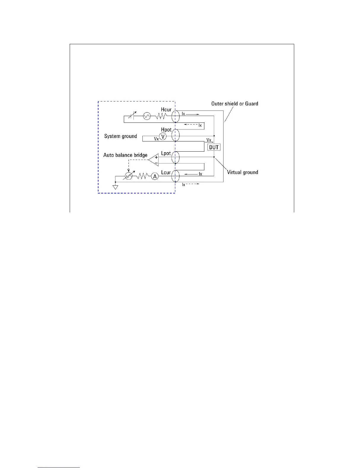
Four-Terminal Pair Configuration
Generally, any mutual inductance, interference of the measurement signals, and unwanted residual
factors in the connection method incidental to ordinary termination methods will have significant
effects on the measurements, especially at a high frequency. The CMU employs the four-terminal
pair (4TP) measurement configuration which permits easy, stable, and accurate measurements and
avoids the measurement limitations inherent to such factors.
The above figure shows the four-terminal pair measurement principle. The measurement terminals
consist of the following four coaxial connectors.
-Hcur: High current
-Hpot: High potential
-Lpot: Low potential
-Lcur: Low current

 Loading...


