Chapter 3 Calibration Procedures
Measurement Techniques
49
3
Measurement Techniques
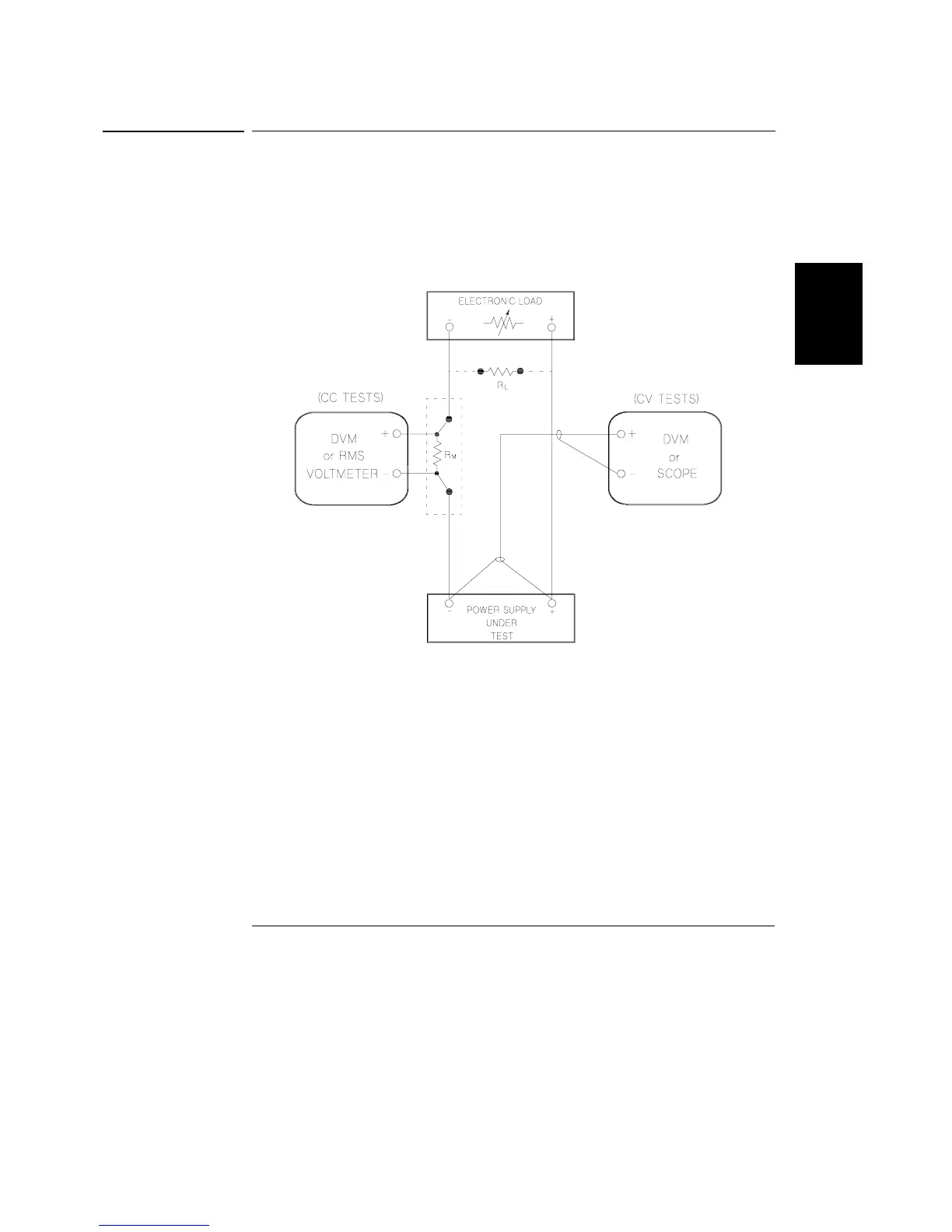
Setup for Most Tests
Most tests are performed at the front terminals as shown in the following
figure. Measure the dc voltage directly at the (+) and (-) terminals on the front
panel.
Figure 3-1. Performance Verification Test Setup
Electronic Load
Many of the test procedures require the use of a variable load resistor capable
of dissipating the required power. Using a variable load resistor requires that
switches should be used to connect, disconnect, and short the load resistor.
An electronic load, if available, can be used in place of a variable load resistor
and switches. The electronic load is considerably easier to use than load
resistors. It eliminates the need for connecting resistors or rheostats in parallel
to handle power, it is much more stable than carbon-pile load, and it makes
easy work of switching between load conditions as is required for the load
regulation and load response tests. Substitution of the electronic load requires
minor changes to the test procedures in this chapter.

 Loading...


