Chapter 11 331
Assembly Replacement Procedures
RF Section E4440A, E4443A, E4445A
Option 123 Dual Mixer
Removal
1. Drop the front frame. See page 314 for instructions.
2. Refer to Figure 11-16. Remove cables W82, W83, and W84.
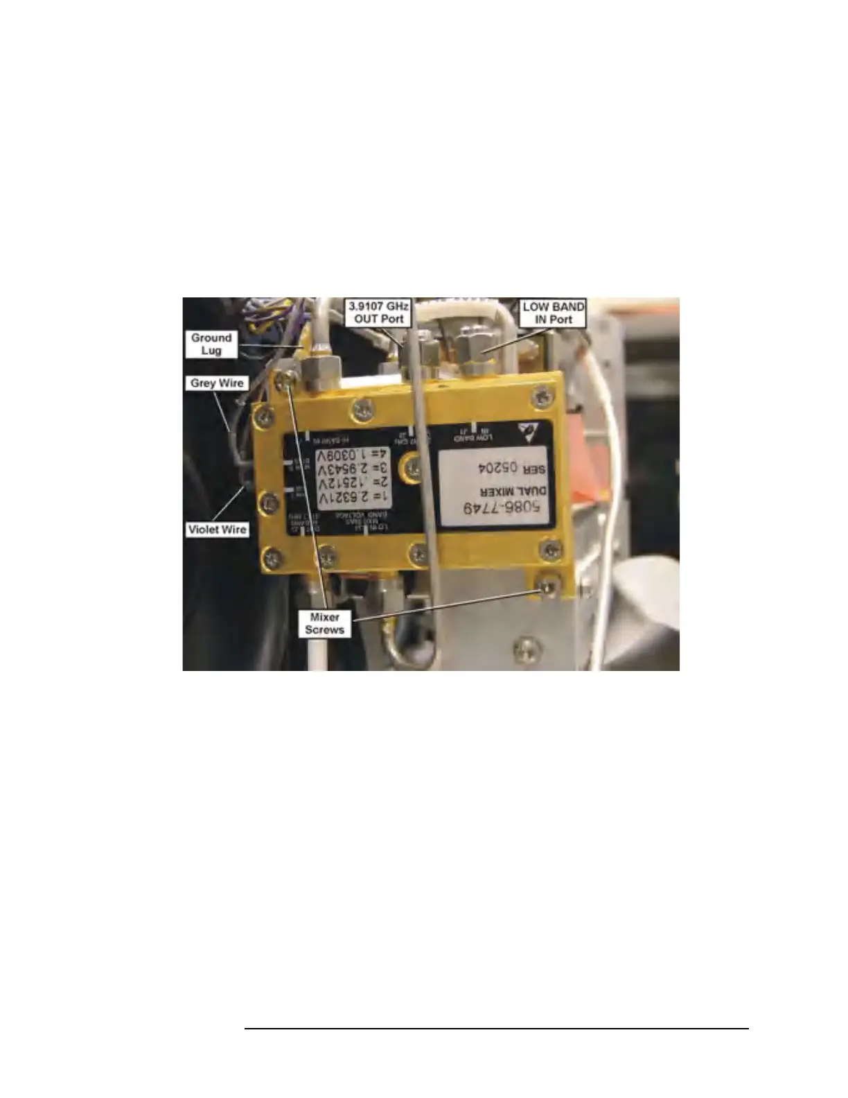
3. Refer to Figure 11-18. Remove the grey and violet wires from the
Dual Mixer connector pins.
Figure 11-18 Dual Mixer
4. Remove the two mixer screws.
5. Remove the two SMA 50 Ω loads from the Low Band In port and the
3.9107 GHz OUT port. Install them on the replacement mixer.
Replacement
1. Attach the Dual Mixer to the end of the switch bracket using two of
the screws as shown in Figure 11-18. Before inserting the top screw,
locate the black wire with the ground lug that is part of the switch
harness. Place the ground lug between the screw head and the mixer
body. Torque the mounting screws to 9 in-lbs.
2. Connect the grey wire with the push on connector to the Dual Mixer
bias pin. Connect the violet wire with the push on connector to the
Pin 7 SW on the Dual Mixer.
3. Replace cables W82, W83, and W84. Torque to 10 in-lbs.
4. Replace the front frame.
 Loading...


