Chapter 4 103
Troubleshooting the RF Section (E4446A, E4447A, E4448A)
RF Section Description (E4446A, E4447A, E4448A)
2. If the problem is in high band or mm band, set the PSA for a start
frequency of 3 GHz and stop frequency of 30 GHz. Verify the
presence of a sweep ramp on the rear panel PRE-SEL TUNE OUT
connector. The oscilloscope display should indicate a series of ramps
and steps ranging from approximately 0 to 5 V. This tune ramp
originates on the A13 Front End Driver assembly and is used to tune
the preselectors in the SBTX/RYTHM assembly.
3. Set the PSA to zero span and use a low loss cable between the
measuring spectrum analyzer and the assembly under test. Set up
the PSA and the signal source as instructed in the block diagram
note (analyzer in zero span, and analyzer and source set to one of
several frequencies that correspond to the different signal paths).
Measure the signal level at the appropriate output port of the
SBTX/RYTHM or cable. Measure the LO input signals at the output
ports of A21 FELOMA.
4. The SBTX and RYTHM must be replaced as an entire unit. It is
possible to remove the A19FL1 cable and confirm a faulty RYTHM or
the SBTX switch. The A19FL1 cable is not separately replaceable.
SBTX Control Verification
Refer to the A29 FELOMA/SBTX driver troubleshooting information on
page 100. Verify that Test Point 4 and Test Point 9 voltages are correct.
A18 YTO
The YTO (YIG-Tuned Oscillator) supplies the raw 3 to 7 GHz LO signal.
Verify that its output is from +12 dBm to +17 dBm. With a DVM, verify
the presence of the supplies on the A13 Front End Driver:
Common symptoms of a faulty YTO are YTO Unlock errors, spurious
signals, and low signal level at all frequencies. Two current-driven coils
are used to tune the YTO. Both coils are used in all spans. The coil
drivers are on the A12 LO Synthesizer assembly and the signals route
through the A13 Front End Driver.
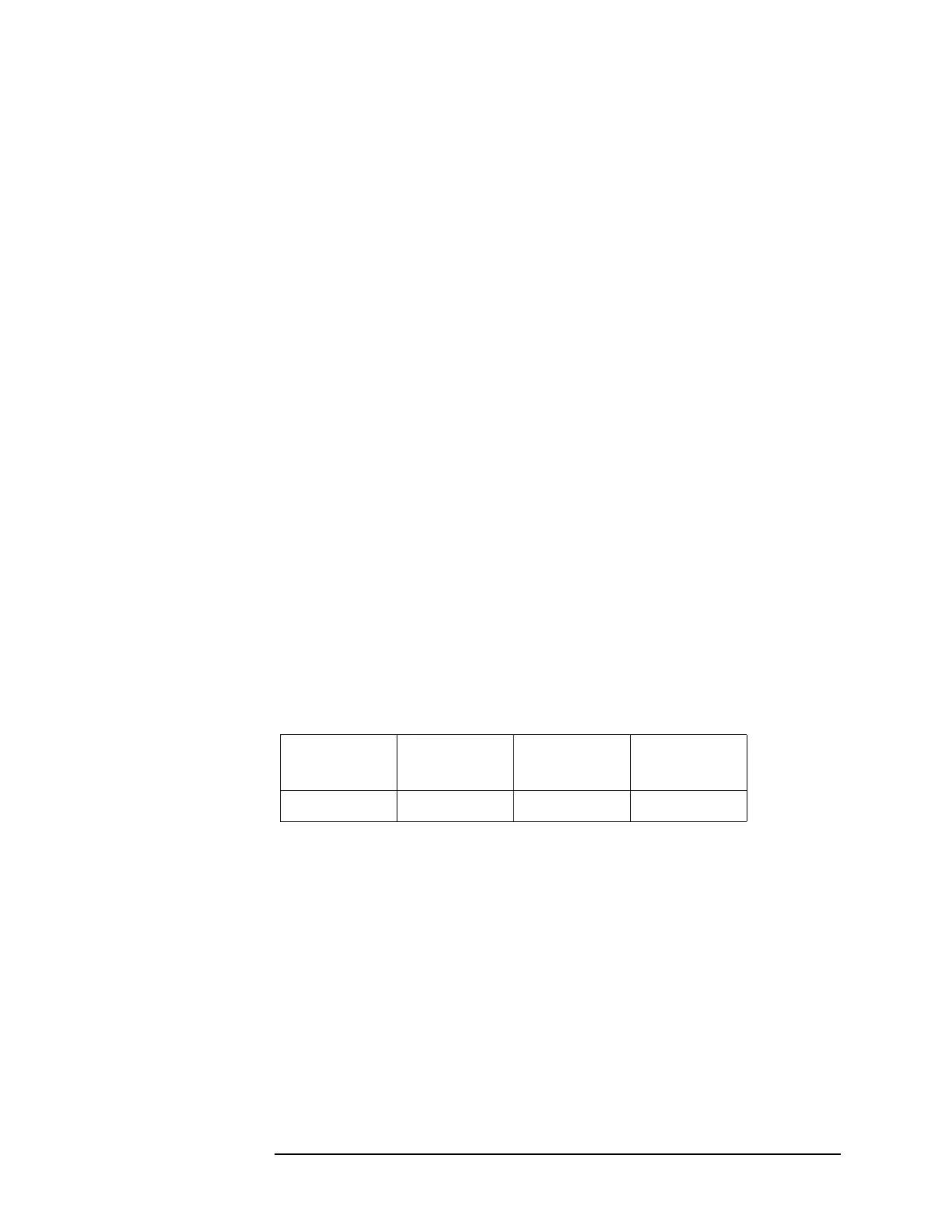
J7
Pin 4
J7
Pin 5
J7
Pin 7
J7
Pin 9
+15 V −5 V +15 V +15 V

 Loading...