Chapter 2 53
Basic Operation
Configuring the RF Output
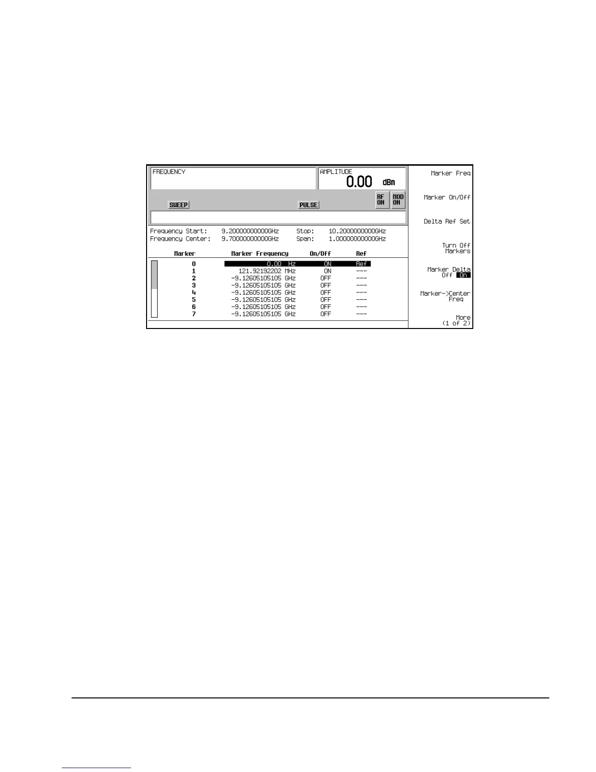
Refer to Figure 2-5.
Figure 2-5 Marker Table Editor
5. Move the cursor back to marker 1 and press
Marker Freq. Turn the front panel knob while
observing marker 1 on the 8757D.
On the 8757D, notice that the displayed amplitude and frequency values for marker 1 are relative
to marker 0 as the marker moves along the trace. Refer to Figure 2- 6.

 Loading...


