Installation Note E8362-90004 19
Step 8. Replace the A38 and A39 Bias Tees (Option UNL Only)
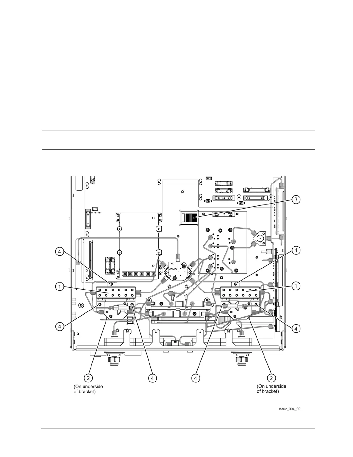
Remove the Detector/Bias Tee/Attenuator Brackets (Refer to Figure 11.)
1. Disconnect all remaining RF cables from each attenuator (item
①) and bias tee (item ②).
2. Disconnect the bias tee control cables at the A16 test set motherboard connectors,
J22 (P1 BIAS T) and J25 (P2 BIAS T), and release them from the cable clamp (item
③).
3. Disconnect the ribbon cables at the step attenuators (item
①).
4. Remove three screws (item
④) from each bracket. Retain the screws for reinstallation.
5. Remove the brackets, with the attenuators and bias tees attached, from the analyzer.
CAUTION
Be careful not to damage the center pins of the semirigid cables. Some flexing of
the cables is necessary when removing the assemblies. Do not over-bend them.
Figure 11 Detector/Bias Tee/Attenuator Brackets Removal
 Loading...

