22 Installation Note E8362-90004
Step 10. Install the Remaining Cables
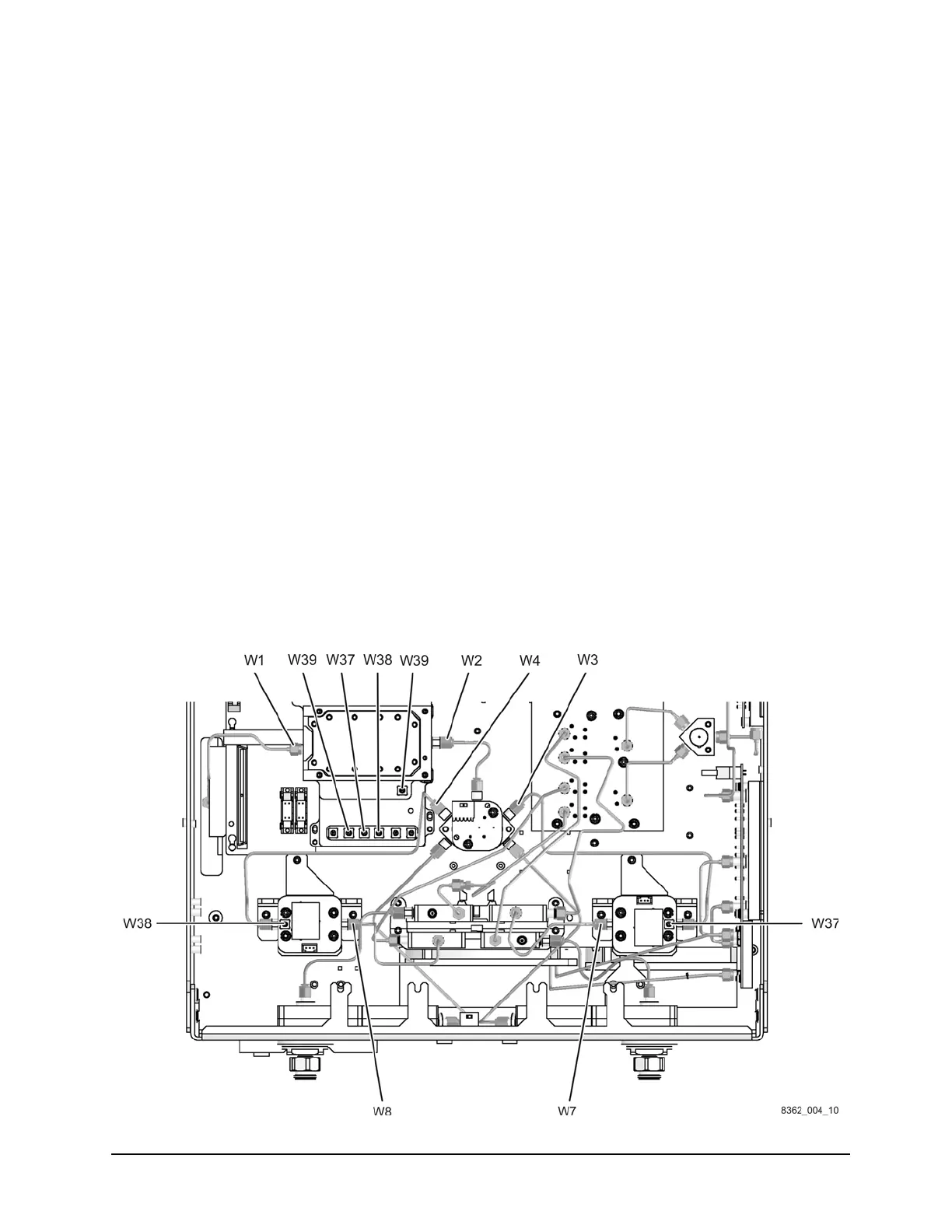
Using a 5/16-inch torque wrench set to 10in-lbs, install the following new cables in the order
listed. These new parts are listed in Table 1 on page 5.
• W1 A12 source 20 to A21 SOMA 50
Connect this cable to the A21 SOMA 50 connector as shown with the other end of the
cable routed through the opening to the top side of the analyzer. The other end of this
cable will be connected later.
• W2 A21 SOMA 50 to A22 switch/splitter
• W3 A22 switch/splitter to A23 channel R1 detector
• W4 A22 switch/splitter to A24 channel R2 detector
• W37 A23 channel R1 detector to A16 test set motherboard J204 (R1)
• W38 A24 channel R2 detector to A16 test set motherboard J205 (R2)
• W39 A21 SOMA 50 to A16 test set motherboard J206 (SOMA 50)
• W7 A23 channel R1 detector to A28 channel R1 mixer
The shape of this cable varies depending upon the option installed. Be sure to install
the correct cable for your analyzer as specified in Table 1 on page 5.
• W8 A24 channel R2 detector to A29 channel R2 mixer
The shape of this cable varies depending upon the option installed. Be sure to install
the correct cable for your analyzer as specified in Table 1 on page 5.
Figure 14 Cables Installation
 Loading...

