5
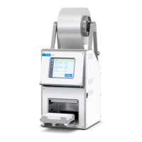
PlateLoc Thermal Microplate Sealer
Optimizing seal parameters
Reference for Optimal Thermal Microplate Sealing
Figure 4 Microplate without and with insert
Figure 5 Standard inserts. The number on the inserts in
dicates the
thickness of the metal pad
(for example, 180 means 0.180 in thick). Note: The 90 insert has a 0
.90-in metal pad with foam
padding on the microplate-facing side and is used with microplates that require flexible support.
Seal material
Different seal materials have different properties and can produce different
results. Perform optimization tests to determine the best seal to use.
Optimizing seal parameters
About this section
This section explains how to inspect the seal quality and, if necessary, how to
adjust the sealing parameters to improve the seal. Before proceeding, download
a copy of the PlateLoc Seal Selection Guide from the Agilent Technologies
website at http://www.chem.agilent.com/
en-us/products/instruments/automation/
microplatehandling/plateloc/pages/default.aspx.
Apply a seal using the time and temperature starting points suggested in the
PlateLoc Sealer Selection Guide, for your chosen seal and microplate material.
Examine the well impressions made on the seal. The pattern and quality of
these impressions is a good indicator of seal quality.
Evaluating the seal
After the seal cycle is finished, wait for the microplate to cool down enough so
that it is safe to handle (10 to 30 seconds). Do not handle the microplate
immediately after the seal cycle is finished. The sealed microplate might be
hot.
Note: Pier
ceable seals might permanently adhe
re to the microplate. Do not wait
too long or the seals will be difficult to remove.
Remove the microplate from the PlateLoc Sealer. Carefully peel off the seal
material
by lifting one of the corners of the seal as shown in Figure 6.
Bend direction
Microplate insert
Wells
 Loading...