PlateLoc Thermal Microplate Sealer
Optimizing seal parameters
6 Reference for Optimal Thermal Microplate Sealing
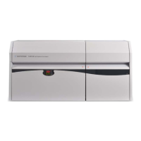
Figure 6 Removing the seal.
Inspect the underside of the removed seal material. If there are unbroken
i
mpressions of each well on the underside of the seal material, the microplate
was properly sealed.
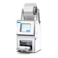
Figure 7 Example of a good seal.
Use a magnifying glass or inspection microscope, if necessary, to see the area
sur
rounding the sample well rim.
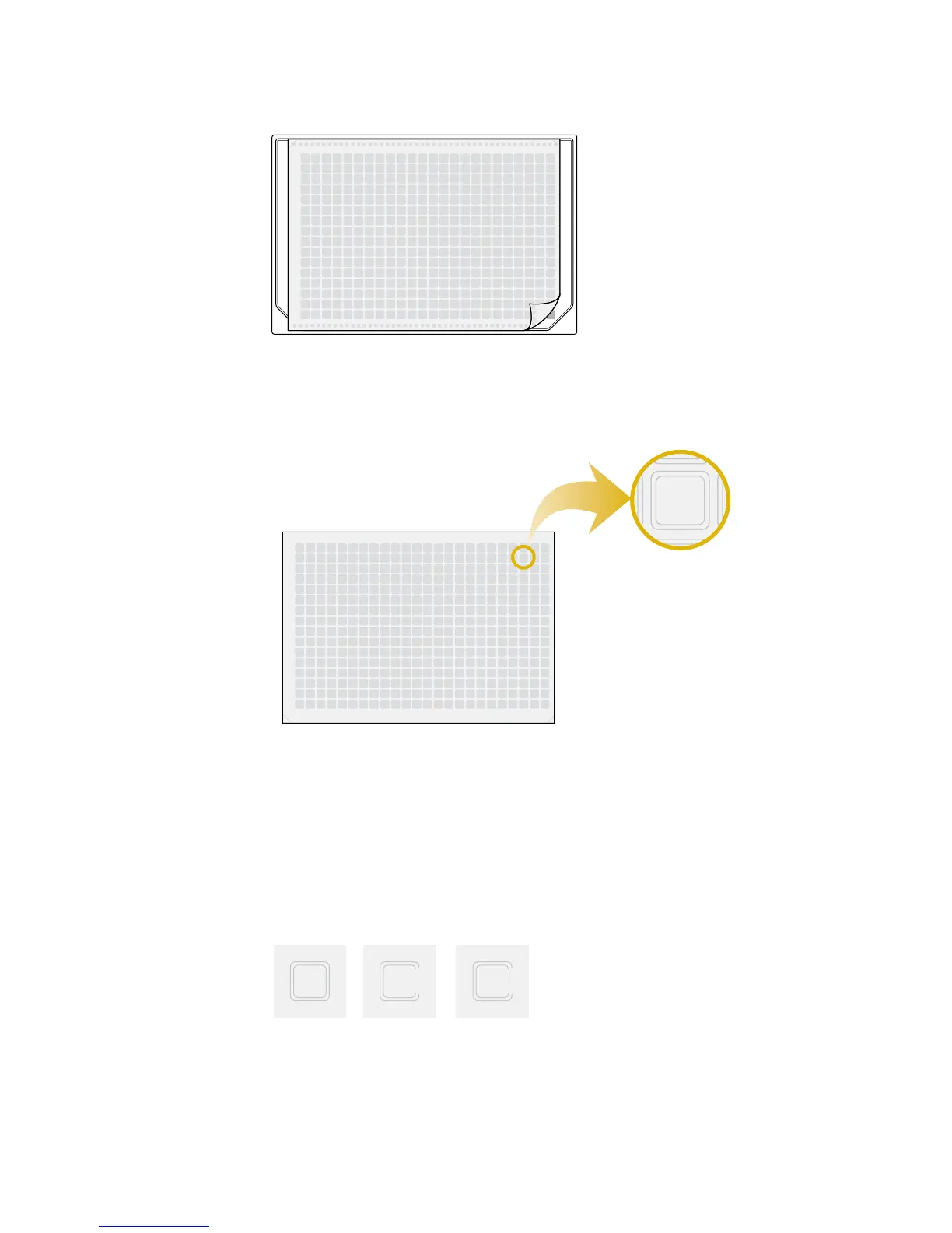
Look closely at a single sample well. A good seal might look like the
illustrations on the left side of Figure 8. The well impression should match the
thickness of the chimney wall, as shown in the left side of Figure 9. A poor
seal might look like the illustrations on the center or right side of Figure 8,
indicating there may not have been enough heat applied to form a complete
impression of the sample well rim.
Figure 8 Evaluating the seals of sample wells. L: Good impression, with defined edge of
chi
mney/rim. C and R: Poor impression, with missing or very faint segments.
If there are faint or broken impressions in the seal material, as shown in
F
igure 8, increase either the sealing temperature or time (duration).
00201
PlateLoc
sealed plate
00201
PlateLoc
sealed plate
 Loading...