AGM Global Vision10
ITEM COMPONENT FUNCTION DESCRIPTION
6
Image transmission
power switch
Powers on/off the image transmission
module.
7 Aviation plug Video and signaling transmission.
8 Aviation plug cover Prevents water or dust.
9 Body
Provides sealing and prevents water or
dust.
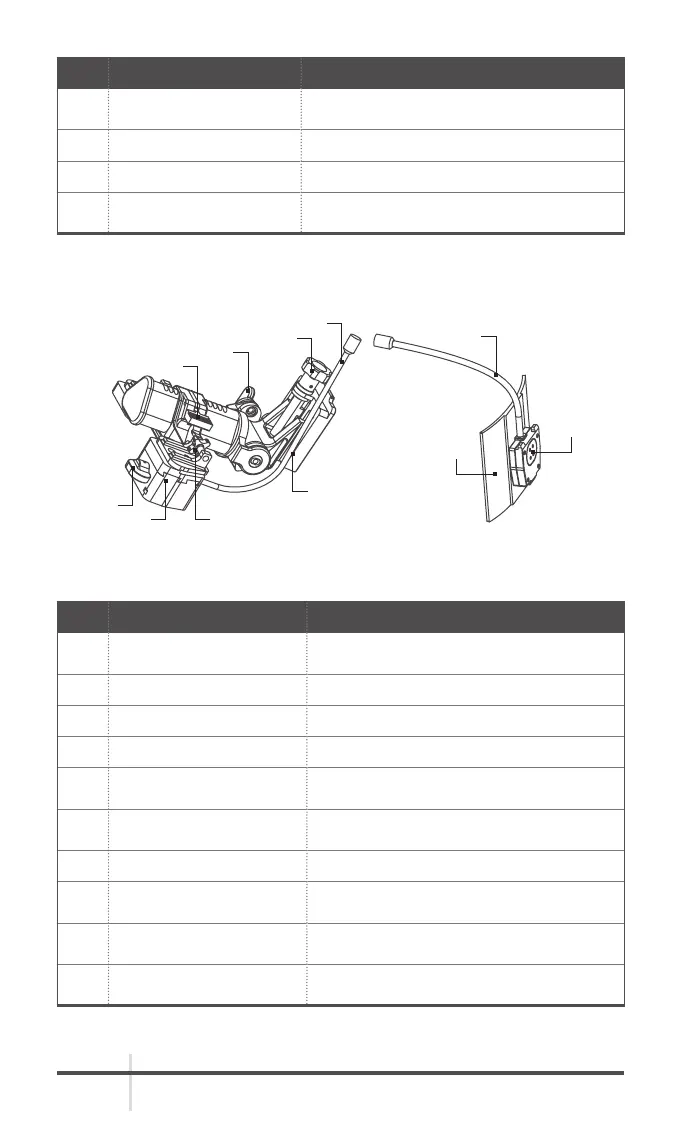
2.1.3 COMPONENTS OF THE HELMET SUPPORT AND THEIR
FUNCTIONS
TABLE 2-2. COMPONENTS OF THE HELMET SUPPORT
ITEM COMPONENT FUNCTION DESCRIPTION
1
Hook-loop support of the
battery holder
Fixes the battery holder on the helmet.
2 Battery holder interface Connects to the battery holder.
3 Goggle interface Connects to the main body of the goggle.
4 Power cable Provides power supply.
5
Helmet installation
interface
Fixes the helmet support on the shroud.
6
Horizontal fine-tuning
buckle
Adjusts the horizontal position of the
goggle.
7 Pitch fine-tuning knob Adjusts the pitch angle of the goggle.
8 Front-back tuning buckle
Adjusts the front and back position of
the goggle.
9
Fixing screw for
switching between eyes
Fixes the goggle either at the right or
left eye.
10 Vertical tuning screw
Adjusts the vertical position of the
goggle.
4
10
7
3
5
6
9
8
1
4
2
FIGURE 2-3. COMPONENTS OF THE HELMET SUPPORT