AIMS Power www.aimscorp.net
position and the inverter stays connected to the battery and the battery voltage doesn’t drop below 2V, the
inverter will be able to charge the battery once qualified AC inputs are present.
Before the battery voltage goes below 9VDC, the charging can be activated when the switch is turned to
“Off”, then to “ON”.
When the voltage goes below 9VDC, and you accidently turn the switch to OFF or disconnect the inverter
from the battery, the inverter will not be able to charge the battery once again, because the CPU loses
memory during this process.
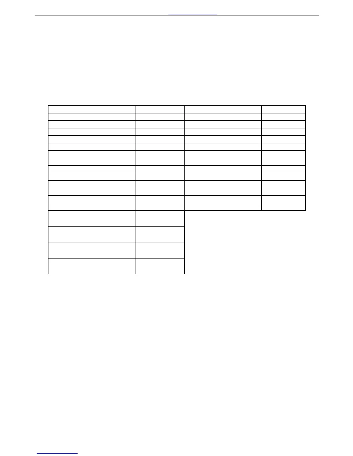
Charging current for each model
Model Current Model Current
PICOGLF10W12V230V 35+/-5A PICOGLF10W12V120V 20+/-5A
PICOGLF10W24V230V 20+/-5A PICOGLF10W24V120V 15+/-5A
PICOGLF15W12V230V 45+/-5A PICOGLF15W12V120V 45+/-5A
PICOGLF15W24V230V 25+/-5A PICOGLF15W24V120V 25+/-5A
PICOGLF20W12V230V 65+/-5A PICOGLF20W12V120V 40+/-5A
PICOGLF20W24V230V 30+/-5A PICOGLF20W24V120V 30+/-5A
PICOGLF20W48V230V 20+/-5A PICOGLF20W48V120V 15+/-5A
PICOGLF30W12V230V 85+/-5A PICOGLF30W12V120V 65+/-5A
PICOGLF30W24V230V 45+/-5A PICOGLF30W24V120V 40+/-5A
PICOGLF30W48V230V 30+/-5A PICOGLF30W48V120V 25+/-5A
PICOGLF40W12V230V 105+/-5A PICOGLF40W12V120V 100+/-5A
PICOGLF40W24V230V 65+/-5A PICOGLF40W24V120V 50+/-5A
PICOGLF40W48V230V 35+/-5A PICOGLF40W48V120V 30+/-5A
PICOGLF50W24V230V
PICOGLF50W24V230VS
70+/-5A
PICOGLF50W48V230V
PICOGLF50W48V230VS
40+/-5A
PICOGLF60W24V230V
PICOGLF60W24V230VS
85+/-5A
PICOGLF60W48V230V
PICOGLF60W48V230VS
55+/-5A
The charging capacity will go to peak charge rate in about 3 seconds. This may cause a generator to drop
frequency, making the inverter transfer to battery mode.
It is suggested to gradually put the charging load on the generator by switching the charging switch from
min to max. Together with the 15s switch delay our inverter gives the generator enough time to spin up.
This will depend on the size of the generator and rate of charge.
2.5.3 Transfer
While in the Standby Mode, the AC input is continually monitored. Whenever AC power falls below the
VAC Trip voltage (154 VAC, default setting for 230VAC,90VAC for 120VAC), the inverter automatically
transfers back to the Invert Mode with minimum interruption to your appliances - as long as the inverter is
turned on. The transfer from Standby mode to Inverter mode occurs in approximately 10 milliseconds. And
it is the same time from Inverter mode to Standby mode.
Though it is not designed as a computer UPS system, this transfer time is usually fast enough to keep your
equipment powered up.
There is a 15-second delay from the time the inverter senses that continuously qualified AC is present at the
10