- 9 -
How to Install
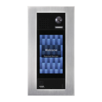
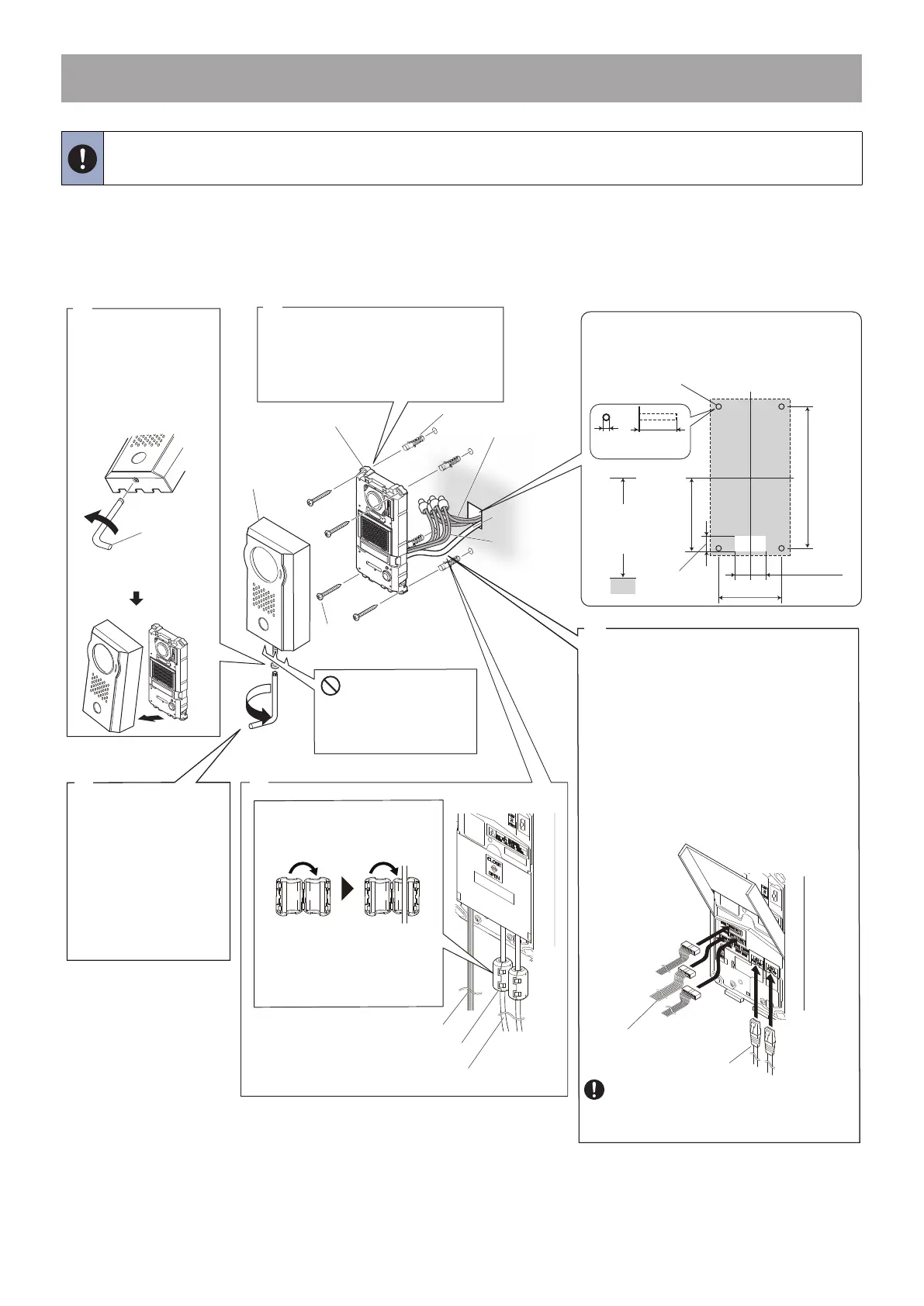
■ Video Door Station Installation
● IX-DV (surface mount)
• The installation height of the equipment should not exceed more than 2m (Upper Edge) from the ground level.
1
4
5
2
Loosen the screw
with the special
screwdriver, and
remove the front
cover.
Loosen
Special
screwdriver
(included)
Vandal-resistant
front panel
Attach the front
cover to the unit by
hanging the upper
2 clips on the unit.
Tighten
Fasten the unit to the
mounting surface.
* Use anchors or concrete plugs
as needed.
Anchors (included) ×4
Option
connectors
(included)
Cat-5e/6 cable
Unit
Wall-mounting screws
(included) ×4
Open the terminal cover, and join
the option connectors (included) to
the low-voltage lines, and insert the
option connectors and Cat-5e/6
cable to the unit.
NOTE
Make room for threading a screw.
Screw mounting
hole ×4
Unit center
Unit
center
86.4 mm (3-3/8'')
60 mm (2-3/8")
30 mm (1-3/16")
182.6 mm (7-3/16'')
95 mm (3-3/4")
Ø 6 mm
(Ø 1/4")
35 mm
(1-3/8")
Moisture drainage holes ×3
Do not block the holes.
Recommended
Mounting height
1,500 mm (4' 11'')
(max.1,850mm (6' 3/4"))
(1) Slide the terminal cover down.
(2) Open up the terminal cover.
(3) Insert the option connectors and Cat-5e/6
cable to the unit, and replace the terminal
cover.
Low-voltage
lines
Clamp the ferrite cores to
Cat-5e/6 cables.
3
* Tighten the screw
with the cover
pressed to the wall.
Open the
ferrite core.
Thread
Cat-5e/6 cable
through the
ferrite core.
Option connectors
Ferrite cores (included) ×2
Cat-5e/6 cable
Option connectors
Cat-5e/6 cable
Be sure to close the terminal cover when
done. If left open, condensation or water
may enter, preventing heat dissipation and
causing damage.
 Loading...