Page
11Air Techniques, Inc.
AS10, AS12, AS21, AS22, AS30,
AS40, AS50, AS70, & AS100
(REAR TABS) A1
(REAR TABS) A1
INSTALLATION INFORMATION
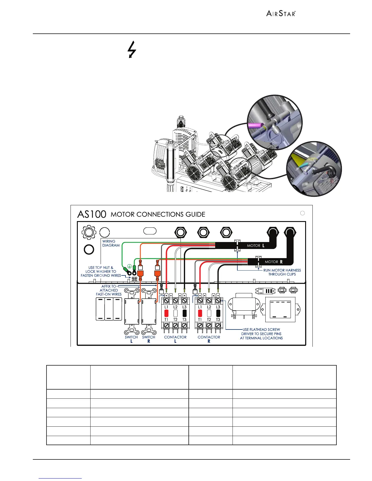
Motor Harness Connections
From
Left Motor
Harness
To Electrical Box
From
Right Motor
Harness
To Electrical Box
Green Ground Green Ground
Orange Switch L Orange Switch R
Gray Contactor L - A1 Tab (under L1) Gray Contactor R - A1 Tab (under L1)
Red Contactor L - L1 Box Lug (over A1) Red Contactor R - L1 Box Lug (over A1)
White Contactor L - L2 Box Lug White Contactor R - L2 Box Lug
Black Contactor L - L3 Box Lug Black Contactor R - L3 Box Lug
Figure 4. Left and Right Head Assembly Motor Connections
Install strain relief to the motor harness of the left and right head assemblies. Connect
each harness as shown by Figure 4. Make sure to run each harness through their
associated clips.
Make sure all system power is removed prior to
working with electrical circuits. Contacting high
voltage can cause serious injury or even death.
Connect air hose A to
left head assembly and
air hose B to right head
assembly.
Air
Hose A
Air
Hose B