Page
7Air Techniques, Inc.
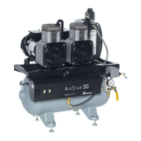
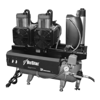
AS10, AS12, AS21, AS22, AS30,
AS40, AS50, AS70, & AS100
AS10, AS12, AS21 and AS22
If a remote Control Panel is being used, the circuit breaker on the face of the
compressor Control box must be in the ON position.
The 24 volt circuit breaker must also be in the ON position. Make sure the reset
button is flush with the face of the circuit breaker. If it isn’t, push it in to reset.
If a Remote Control Panel is not being used, be sure that the yellow and the
orange wires are connected to one another. These wires are located in the
pressure switch. The circuit breaker located on the face of the compressor
Control Box is the power control for the motor.
AS30, AS40, AS50, AS70 and AS100
If a Remote Control Panel is being used, ALL switches on the face of the com-
pressor Control Box must be in the ON position.
If a Remote Control Panel is not being used, be sure that the yellow and the
orange wires are connected to one another. These wires are located on the pressure
switch. The power switches located on the face of the compressor Control Box are
the power control for each motor.
Note: Compressor motors are designed to run together. Do not run one head
at a time unless one head has failed and you are waiting for service.
The motor circuit breaker must be kept in the ON position and should not be used
as a switch.
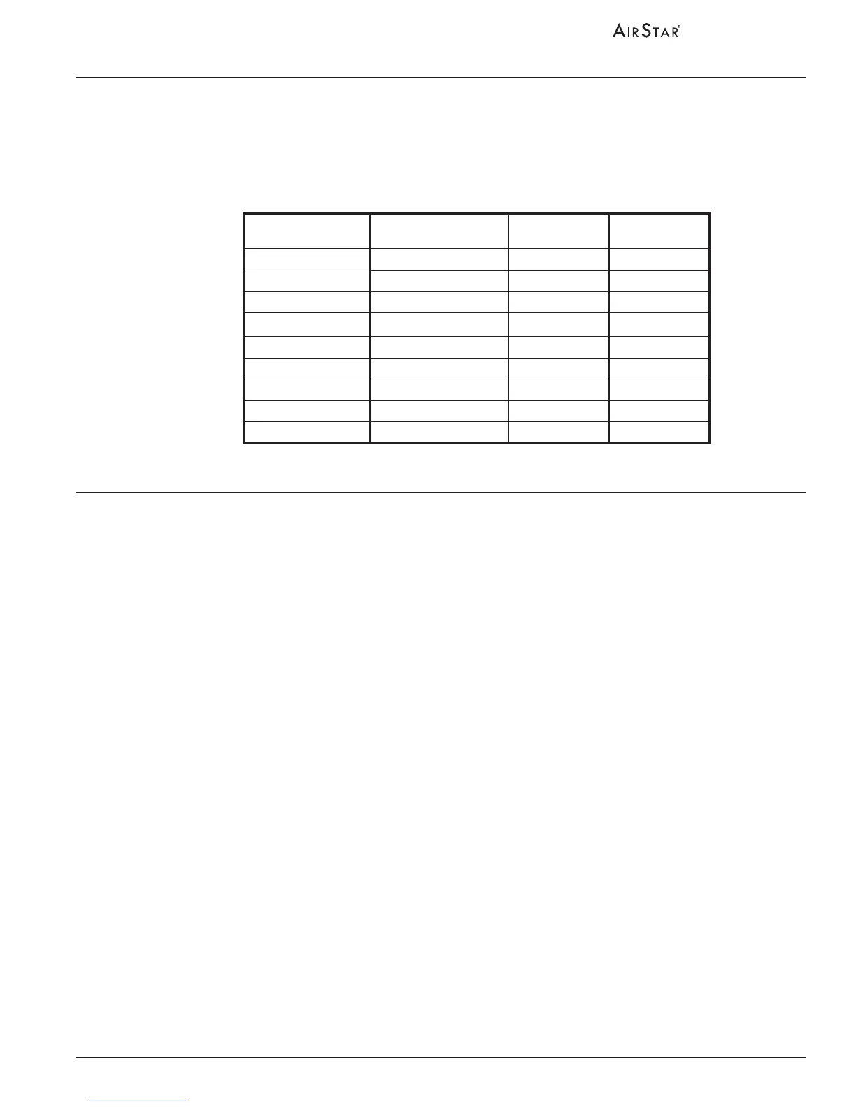
OPERATING INFORMATION
Choosing the correct size AIRSTAR for your practice depends on the number of air users and
the anticipated air demand. To assure optimum compressor operation, the air demands should
not exceed the number of air handpiece users shown in the chart below:
Model
Recommended
Number of Users
Number of
Heads
Number of
Motors
AS10 1 - 2 1 1
AS12 1 - 2 1 1
AS21 2 - 3 2 1
AS22 2 - 3 2 1
AS30 3 - 4 2 2
AS40 4 - 5 3 2
AS50 5 - 7 4 2
AS70 7 - 10 6 3
AS100 10-14 8 2
SIZING GUIDE