Page
13Air Techniques, Inc.
AS10, AS12, AS21, AS22, AS30,
AS40, AS50, AS70, & AS100
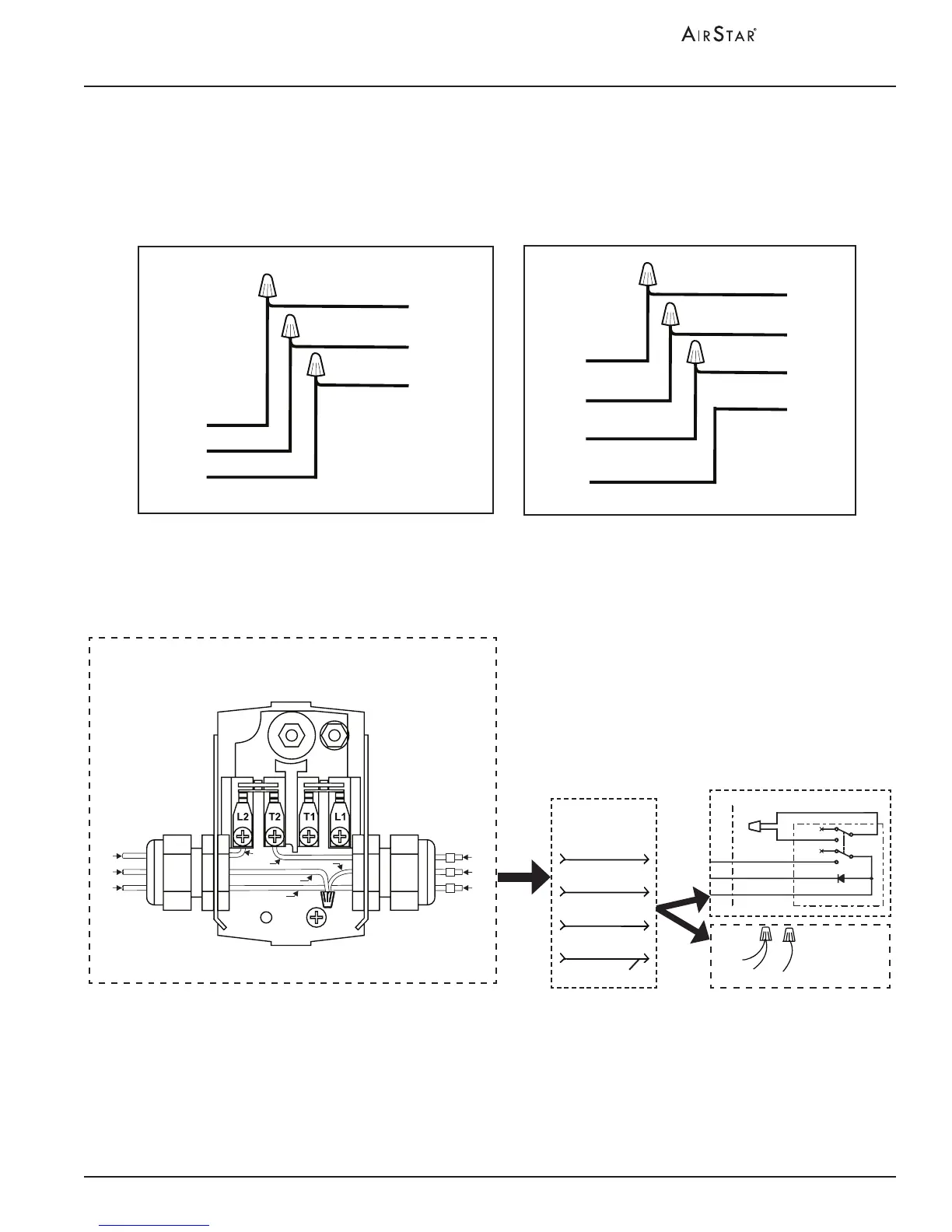
24VDC CONNECTIONS: 24VDC connections are used when installing a 24VDC
remote switch. Make the 24VDC connections shown by Figure 3 for the remote
switch. When not using the remote switch, insulate the BRN wire and tie the ORG
and YEL wires together.
Figure 5. Airstar Electrical Connections
INSTALLATION INFORMATION
24VDC Connections
Notes:
1. Use 18 Gauge, 4 conductor, interconnect cable between the
AirStar unit and Remote Switch Panel.
When any 24V circuit exceeds 150 feet, use #16 AWG.
2. As shown, 3 conductors of the 24V circuit cable from each compressor
connect via the user-supplied interconnect cable.
3. The fourth conductor of interconnect cable to be used for future
equipment options/enhancements.
4. Leave with factory connection, without a 24 V Switch, or connect
the associated interconnect cable directly to remote switch.
Please note that one switch is used for each compressor.
Interconnect
Cable
Yellow 2
Brown 4
Orange 3
See Note 3
Future Use
Remote Panel
Yellow 2
Brown 4
Orange 3
White
White
See
Note 4
Connection
without
24 V Switch
4 BRN
3 ORG
2 YEL
From
Electrical Box
2
4
3
ORN
YEL
BRN
BLU
BLK
BRN
YEL
BLK
BRN
BLU
ORN
Pressure Switch
To Remote
Panel
AS100
3-Phase Electrical Connections
AS50 and AS70
Electrical Connections
BLUE
L1
L2
GND
L3
GREEN
BLACK
RED
RED
BLACK
BLUE
L4
GREEN
L1
L2
GND
WHITE
GREEN
BLACK
WHITE
BLACK
GREEN
HARD WIRED
CONNECTED
AIRSTAR MODELS
AS50 & AS70
HARD WIRED
CONNECTED
AIRSTAR MODEL
AS100