32
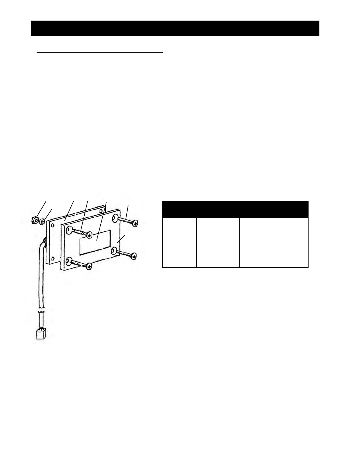
FIGURE 18
LIQUID CRYSTAL DISPLAY (LCD)
1. Ensure that the power switch is OFF and that the machine is unplugged.
2. Detach the pressure control assembly (Fig. 12, Item 301-318-99) from the frame by unscrewing
the eight screws (Fig. 13, Item 111-037).
3. Disconnect the LCD lead from the the pressure control assembly.
4. Separate the LCD assembly from the frame by undoing the four screws (Fig. 18 Item 6)
5. Disassemble Items 1-6 (Fig 18)
6. Remove and replace LCD Display (Fig. 18 Item 3).
7. Reassemble in reverse order.
NOTE: Do not over tighten the screw and nuts (Fig 18, Item 1 & 6).
This can warp the LCD and damage it.
8. Perform "LCD Calibration Procedure". See page 25.
REPLACEMENT OF ELECTRICAL COMPONENTS
FIGURE 18 PARTS LIST
ITEM # PART # DESCRIPTION
1
2
3
4
5
6
*
Nut (4)
Plastic Washer (4)
Display Board Ass'y
Spacer (4)
Window
Screw (4)
Frame
117-126
120-046
331-377
117-281
331-360
100-362
1
2
3
4
5
6
*