Do you have a question about the AIRLESSCO LP400 ALLPRO 410E and is the answer not in the manual?
Technical specifications including motor type, pressure, output, and tip size.
Lists materials such as oil base coatings, sealers, and varnishes compatible with the sprayer.
Critical safety warning about high pressure spray and potential for serious injury.
Explains symbols like WARNING, CAUTION, IMPORTANT, and NOTE used for clarity.
Provides emergency medical care instructions for fluid injection injuries from the sprayer.
Lists precautions to prevent injection injuries, such as not pointing the gun at the body.
General safety guidelines including not altering equipment and wearing protective gear.
Specific advice for doctors treating injection injuries, emphasizing prompt treatment.
Safety measures for the spraying area, including ventilation and avoiding flammables.
Safety guidelines for using and servicing the spray gun, including latching.
Emphasizes the use of the tip guard to prevent accidental contact with the spray tip.
Precautions for cleaning and changing spray tips, including pressure relief.
Safety procedures for dealing with toxic fluids and fumes, including PPE.
Guidelines for hose inspection, use, and replacement to prevent rupture and injury.
Instructions on grounding the sprayer and system components to prevent static sparks and fire.
Warning to keep clear of moving parts during operation and servicing.
Precautions to prevent component rupture due to pressure or improper use.
Measures to prevent fire and explosions caused by static sparks, including grounding and ventilation.
Safety precautions during the flushing process, especially with flammable materials.
Detailed safety steps for spraying and cleaning with flammable liquids.
Instructions for flushing a new sprayer before first use with different paint types.
Procedure for flushing the sprayer when changing paint colors.
Steps to flush the sprayer when switching from water-base to oil-base paint.
Steps to flush the sprayer when switching from oil-base to water-base paint.
Flushing procedures for storing the sprayer, including protection for long-term storage.
Flushing instructions after the sprayer has been stored.
Critical warning against leaving the pump unattended while under pressure.
Step-by-step guide on how to flush the sprayer, including control descriptions.
Initial step for flushing: engage gun safety latch and remove spray tip.
Prepare a pail with sufficient clean, compatible solvent for flushing.
Position the suction tube into the solvent pail.
Set the Prime/Pressure Relief Valve to the OPEN position for priming.
Aim the gun into the pail and ensure metal-to-metal contact for safety.
Disengage safety latch, squeeze trigger, turn on unit, and adjust pressure to start pump.
Close the Prime/PR Valve to flush solvent through the system until clean.
Release the trigger and re-engage the gun safety latch after flushing.
Reminds users to follow the pressure relief procedure when shutting down.
Warning about static sparking during flushing and the importance of metal-to-metal contact.
Instructions for connecting the airless hose and spray gun, including hose type recommendations.
Procedure for filling the packing nut/wet cup with TSO for lubrication.
Verification of electrical service requirements, including voltage and grounding.
Critical steps for grounding the sprayer and system to prevent static discharge and fire hazards.
Instruction to flush the sprayer according to the flushing procedure.
Warning about static sparking, fire, or explosion risks and the necessity of grounding.
Familiarization with the functions of the PRIME/PRESSURE RELIEF VALVE and other controls.
Steps for preparing the spray material and placing the suction tube in the container.
Step-by-step guide to start the sprayer after preparation, including control settings.
How to adjust spray pressure using the control knob for optimal atomization.
Method to keep the spray tip clean by submerging the gun in thinner when not in use.
Warning to relieve pressure before adding pump conditioner.
Warning about injection hazards when checking or cleaning the spray tip.
Safety precautions when spraying into the paint bucket, including pressure and grounding.
Steps for safely shutting down the sprayer, including flushing and pressure relief.
Instructions for stopping the unit in an emergency, including motor shutoff and pressure relief.
Emphasizes the importance of following the pressure relief procedure to avoid serious injury.
Daily maintenance tasks, including lubricating the packing nut and inspecting it.
Instructions for attaching the spray gun and using the gun safety latch.
Identifies the main components of the spray gun and reversible spray tip.
Step-by-step guide for assembling the spray tip and guard onto the gun.
Procedure for removing clogs from the spray tip, including unlocking the handle.
How to clean the spray gun immediately after use with solvent.
Instructions for cleaning the filter located inside the gun handle.
Advice on handling a clogged spray tip, including pressure relief and cleaning methods.
Lists common problems encountered with the airless spray gun.
Explains the potential causes for each spray gun problem listed.
Provides recommended solutions and corrections for spray gun issues.
Guidance on selecting spray tips based on paint viscosity, type, and job requirements.
Explanation of how pattern width is determined and its effect on coverage.
How different tip sizes and widths affect paint application over an area.
Advice on replacing worn spray tips to maintain performance and prevent wasted paint.
Explains how to identify spray tip part numbers, fan width, and orifice size.
Chart detailing orifice sizes for painting tips based on fan width.
Information on available gun filter mesh sizes (Coarse and Fine).
Guides for selecting spray tips based on the material being sprayed (e.g., wood, masonry).
Table showing water flow rates for different spray tip orifice sizes.
Table showing paint flow rates for different spray tip orifice sizes.
Minimum pump output required for various spray tip sizes.
Chart detailing orifice sizes for striping tips based on fan width.
Details for REV-TIP™ part numbers for paint spraying, including components.
Details for REV-TIP™ part numbers for striping applications.
Information on Fine Finish REV-TIP™ with double orifice design for smoother finishes.
Notes that the motor has pre-lubricated ball bearings for life.
Guidance on periodic inspection and replacement of motor brushes based on wear.
Detailed steps for replacing the motor brushes, including unplugging and reassembly.
Important note on the run-in period required for new brushes to ensure longevity.
Lists common operational problems encountered with the sprayer unit.
Explains the potential causes for each troubleshooting problem.
Provides recommended solutions and fixes for the identified sprayer problems.
Warning against operating the machine without the cover guard in place for safety.
List of part numbers and descriptions for the gear and pump assembly components.
Illustration showing the components of the gear and pump assembly.
Step-by-step instructions for disassembling, inspecting, and servicing the gearbox.
Specific procedure for replacing the sleeve bearing in the gearbox assembly.
List of parts required for gearbox sleeve bearing replacement.
Note advising to check the troubleshooting chart before disassembling the fluid pump.
Detailed steps for removing the fluid pump from the machine, referencing Figure 11.
Illustration showing the components involved in fluid pump removal.
Step-by-step guide for reinstalling the fluid pump assembly, referencing Figures 11 and 14.
Procedures for disassembling the outlet valve, including parts identification.
Illustration of the outlet valve components for servicing.
Steps for servicing the suction assembly, including cleaning and reassembly.
Illustration of the suction assembly components for servicing.
Refers to previous steps for fluid pump removal.
Detailed steps for disassembling the fluid pump, referencing Figure 16.
Refers to previous steps for outlet valve disassembly.
Step-by-step guide for reassembling the packing glands and components, referencing Figures 15 and 16.
Refers to previous steps for fluid pump reinstallation.
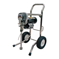
Illustration of the sprayer's frame assembly with numbered components.
List of part numbers and descriptions for the frame assembly components.
Illustration of the suction assembly components with numbered parts.
List of part numbers and descriptions for the suction assembly components.
Identifies potential causes for the sprayer machine failing to start.
Provides a sequence of steps to diagnose and resolve the machine not starting issue.
Steps for calibrating the pressure control system after component replacement.
General warning and notes for replacing electrical components safely.
Procedure for replacing the electrical control board.
Steps for removing and replacing the pressure control knob.
Procedure for replacing the ON-OFF toggle switch.
Steps for replacing the fuse holder assembly.
| Brand | AIRLESSCO |
|---|---|
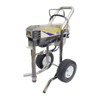
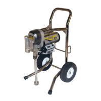
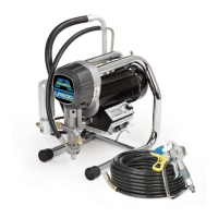
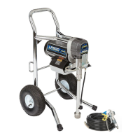
| Model | LP400 ALLPRO 410E |
| Category | Paint Sprayer |
| Language | English |