Do you have a question about the AirMan PDS400S-6C3 and is the answer not in the manual?
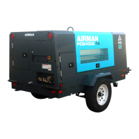
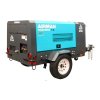
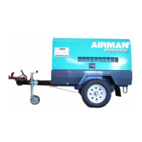
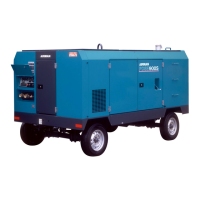
Lists physical and operational specifications for the compressor and engine.
Details critical set values for various operational parameters and warnings.
Identifies and labels internal components of the machine with corresponding numbers.
Details the layout and functions of the unit's operation panel and indicators.
Provides essential safety and procedural precautions before and during maintenance.
Specifies torque values for various bolts and nuts during assembly and repair.
Overview of the engine's electronic control system and its constituent parts.
Details the common rail fuel injection system and its components.
Provides details on the Engine Control Module (ECM), its connectors, and functions.
Information regarding the emergency controller and its role in safety shutdowns.
General guidelines and procedures for performing repairs and fault diagnosis.
Critical safety precautions to be observed during repair and diagnostic work.
Provides essential precautions and guidance for accurate failure diagnosis.
Explains how to interpret and utilize the troubleshooting flowcharts and diagrams.
Categorizes common failures related to the compressor and engine systems.
Describes the unit's behavior and troubleshooting when emergency switches are activated.
Troubleshooting for engine shutdown due to high discharge/separator air temperature.
Troubleshooting engine shutdown caused by low engine oil pressure warnings.
Troubleshooting engine shutdown due to high engine coolant temperature.
Diagnosing engine shutdown when engine RPM drops unexpectedly.
Details how to use the engine's integrated trouble diagnosis and flash code system.
| Brand | AirMan |
|---|---|
| Model | PDS400S-6C3 |
| Category | Air Compressor |
| Language | English |