AS-D+—AS-P Series Instruction Manual 169
AirSep Corporation
Pag e 2 of 4
I&M No. V6941R4
EASCO Valve, Inc.R 50 Hanover Road, Florham Park, New Jersey 07932 www.ascovalve.com
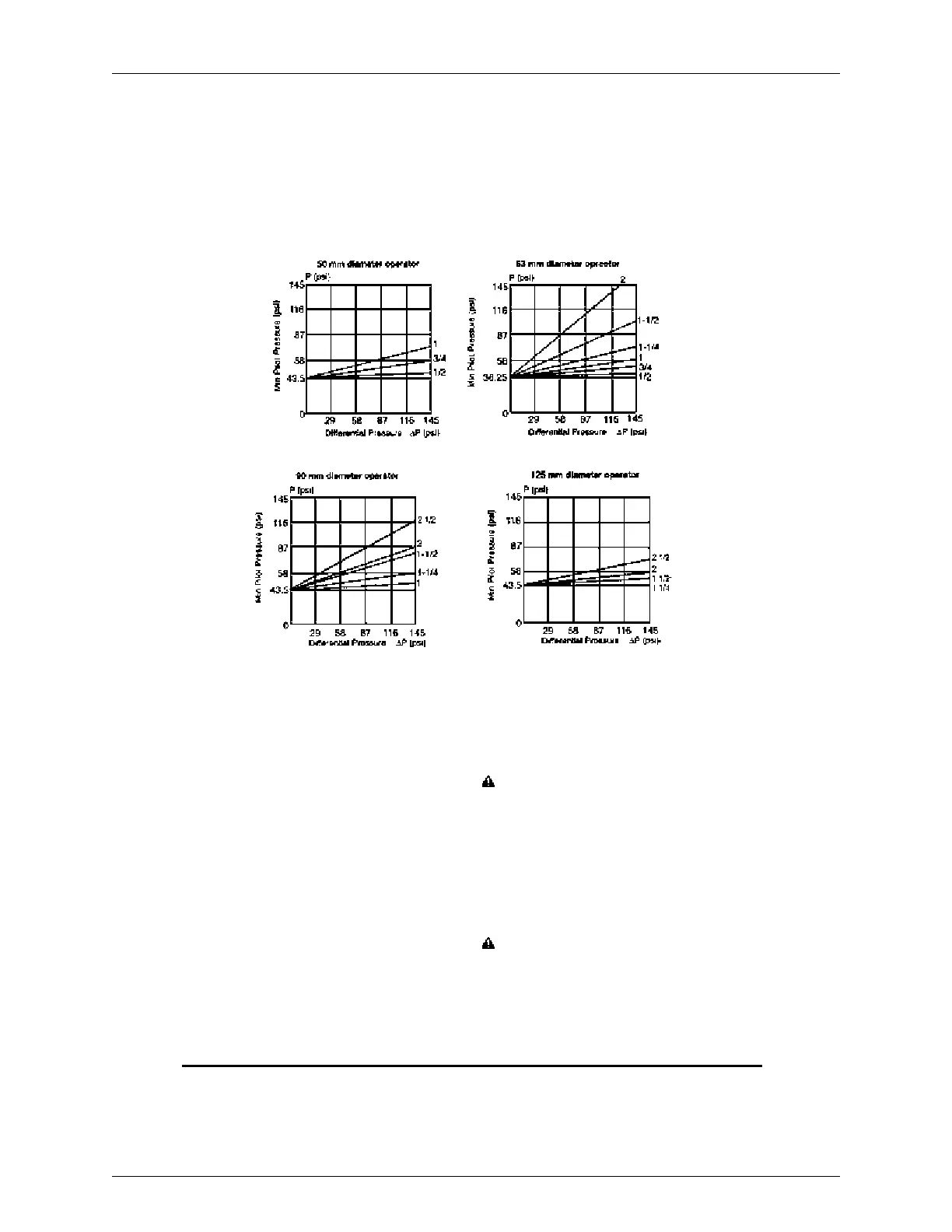
Normally Closed Valves -- Steam Servi ce (entry above disc)
Normally closed -- (entry under disc) Minimum pilot pressure is 58 psi; maximum 145 psi.
INSTALLATION
Check nameplate for correct catalog number, pressure (main and
auxiliary), temperature and service. Never apply incompatible fluids
or exceed pressure rating of the valve. Installation and valve
maintenance to be performed by qualified personnel.
Future Service Considerations
Provision should be made for performing seat leakage, external
leakage and operational tests on the valve with a nonhazardous,
noncombustible fluid after disassembly and reassemb ly.
Temperature Limitations --- Main Valve
S Ambient Temperature Range:
12_F ( --- 1 0 _C) to 140_F (60_C)
S Fluid Temperature Range:
12_F ( --- 1 0 _C) to 356_F (180_C)
Positioning
This valve is designed to perform properly when mounted in any
position.
Pilot Valve Installation (General)
For ease of access to solenoid pilot valve and auxiliary piping
alignment, the piston operator with the pilot port connection may be
rotated 360_.
Remove the plastic protective plug from the pilot port. See separate
instructions and drawings covering normally closed and normally
open operation. Then follow the connection procedures for the
appropriate version:
Connection of the pilot valve
S to the 1/8I NPT port (for 50 or 63 mm operator), see separate
instructions for pilot v alves.
S to the 1/4I NPT port (for 90 or 125 mm operator), see separate
instructions for pilot v alves.
CAUTION: The exhaust port plug mounted by the
manufacturer must never be removed.
Connect piping to valve according to markings on valve body.
Pressureis at Port 2 (entry under disc) for all liquids and gases. For
rapid cycling steam valves pressure is at Port 1 (entry above disc).
Apply pipe compound sparingly to male pipe threads only. If
applied to valve threads, the compound may enter the valve and
cause operational difficulty. Avoid pipe strain by properly
supporting and aligning piping. When tightening the pipe, do not
use valve or piston operator head as a lever. Locate wrenches,
applied to valve body or piping, as close as possible to connection
point.
CAUTION: To protect the piston operated valve,
install a strainer or filter suitable for the service
involved in the inlet side as close to the valve as
possible. Clean periodically depending on service
conditions. See ASCO Series 8600, 8601 and 8602 for
strainers.
Pag e 3 of 4
I&M No. V6941R4
EASCO Valve, Inc.R 50 Hanover Road, Florham Park, New Jersey 07932 www.ascovalve.com
MAINTENANCE
WARNING: To prevent the possibility of death,
serious injury or property damage, turn off electrical
power, depressurize valve (main and auxiliary), and
vent fluid to a saf e area before servicing the valve.
NOTE: It is not necessary to remove the main valve from the pipeline
for repairs. However, the piping or tubing and electrical connections
must be disconnected from the solenoid pilot valve. See separate
instructions.
Cleaning
All valv es should be cleaned periodically. The time between cleaning s
will vary depending on the medium and service conditions. In general,
sluggish valve operation, excessive noise or l eakage will indicate that
cleaning is required. In the extreme case, faulty valve operation will
occur and the valve may fail to open or close. Clean strainer or filter
when cleaning the valve.
Preventive Maintenance
S Keep medium flowing through the valve as free from dirt and
foreign material as possible.
S Periodic exercise of the valve should be considered if ambient or
fluid conditions are such that corrosion, elastomer degradation,
fluid contamination build up, or other conditions that could
impede solenoid valve shifting are possible. The actual frequency
of exercise necessary will depend on specific operating conditions.
A successful operating history is the best indication of a proper
interval between exercise cycles.
S Depending on the medium and service conditions, periodic
inspection of internal valve parts for damage or excessive wear is
recommended. Thoroughly clean all parts. If parts are worn or
damaged, install a complete rebuild kit.
Causes of Improper Operation
S Incorrect Pr essure: Check valve pressure. Pressure to valve must
be within range specified on nameplate.
S Excessive Leakage: Disassemble valve and clean all parts. If parts
are worn or damaged, install a complete ASCO Rebuild Kit.
Valve Disassembly and Reassembly
1. Disassemble valve in an orderly fashion using exploded view for
identification and placement of parts.
2. Disconnect piping and wiring from solenoid pilot valve. See
separate instructions.
3. For normally closed valves, the operator must be pressurized
prior to unscrewing the stuffing box. It should remain
pressurized during reinstallation.
4. Remove the piston operator and stuffing box packing with a
wrench (a).
5. Unscrew the disc nut with a wrench (b).
6. Clean all accessible parts.
7. Replace parts numbers 1, 2, 3 and 4 with the corresponding
parts from the ASCO Rebuild Kit.
8. Reassemble the parts and observe the indicated tightening
torques.
9. Reinstall piping and make electrical connection to solenoid
pilot valve. See separate instructions.
WARNING: To prevent the possibility of death,
serious injury or property damage, check valve for
proper operation before returning to service. Also
perform internal seat and external leaka ge tests with a
nonhaza rdous, noncombustible fluid.
10 . Restore pressure (main and auxiliary) and electrical power
supply to solenoid pilot valve.
11. After maintenance is completed, operate the valve a few times
to be sure of proper operation.
ORDERING INFORMATION
FOR ASCO R EBUILD KITS
When Ordering Rebuild Kits for ASCO valves, order the Rebuild Kit
number stamped on the valve nameplate. If the number of the kit is
not visib le, order by indicating the number of kits required, and the
Catalog Numb er and Serial Number of the valve(s) for which they are
intended.
Normally Open Pilot (entry under disc)
Normally Closed Pilot (entry under disc)
Normally Closed Pilot (entry above disc)
50
63-- 90-- 125
50
63-- 90-- 125
50
63-- 90-- 125