28 AS-D+—AS-P Series Instruction Manual
AirSep Corporation
7. Release pressure and check a few points in the range and ensure the
reading is close. If it is off return to step 3.
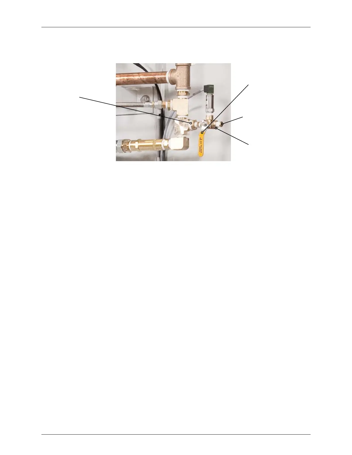
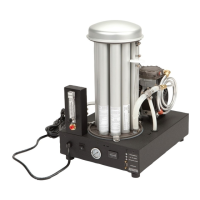
Oxygen
Generator
Manifold
Connection
Direction of ow
path shown
from oxygen
generator to
pressure
transducer
Port A (shown open
to atmosphere
unless calibrating)
V-A
Figure 4.9: Feed Air Pressure Transducer Assembly
8. Disconnect the manual air pump from port A and put the plug, if any,
back to port A.
9. Open the manual three-way valve (V-A), so that the flow path is from
the oxygen generator to the pressure transducer as shown in Figure
4.9.
Press the ‘NEXT’ icon to navigate the calibration screen for Bed B and the oxygen
receiver pressure transducer.
4.6 CONTROL PANEL: INTERNAL COMPONENTS
The internal layout of the control panel mainly consists of the programmable logic
controller (PLC), oxygen concentration board (optional), HMI, circuit breakers,
transformers, and an alarm horn.
Programmable Logic Controller
The programmable logic controller contains the logic for the oxygen generator
operation.
Oxygen Concentration Monitoring Board
This board monitors the concentration of the product oxygen. A sample of product
oxygen ows from the oxygen receiver to this board through a regulator. Ensure
that the regulator is set for ~1 psig for accurate readings. Refer to Figure 4.1 for the
location of the regulator.
Human Machine Interface (HMI)
The HMI acts as an interface between the operator and the oxygen generator.