14-1
SERVICING
SM DLSDCI 3-A.1 GB
14. SERVICING
14.1 Outdoor Unit DLS 36/43
TURN OFF ALL POWER SOURCE BEFORE HANDLING THE UNIT
Note: To reassemble perform the procedures in reverse.
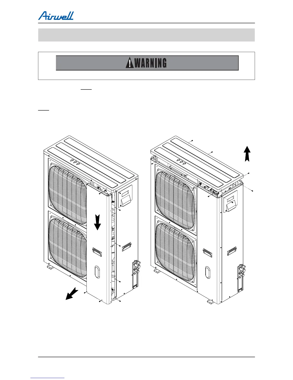
14.1.1 Removing Service (front) panel
Remove the 8 xing screws and slide the service (front) panel downwards to remove it.
Note: Do not ip the panel forward on the top side as not to damage the controller.
14.1.2 Removing top panel
Remove the 8 xing screws and take out the top cover.
Removing Service (front) panel Removing Top panel
TROUBLESHOOTING
Service Manual
Multi Trio-72/Quattro-80 DCI 13-28 Revision 0
13.5 Procedures for checking Main Parts
13.5.1 Discharge DC Voltage
13.5.2 Checking Mains Voltage
Confirm that the Mains voltage is between 198 and 253 VAC. If Mains voltage is out of this range,
abnormal operation of the system is expected. If in range, check the Power (Circuit) Breaker and
look for broken or loosed cable lugs or wiring mistakes.
13.5.3 Checking Line Filter Board
1) Check for any burn signs on the filter board and its coils and relays, replace if any.
2) Check voltage at the inlet and outlet of the line filter. If no output voltage, replace line filter.
Replacing line filter - (14.1.19)
13.5.4 Checking Inrush Circuitry
1) Check continuity of each wire on the inrush wiring cable – repair if needed.
2) Power ON the unit, check voltage between both of the inrush pins on the ODU main board –
should be 0 at first and 12VDC after 1 minute. A click sound should also occur after 1 minute. If
no voltage – replace ODU main Board.
3) While power is off check resistance between line input and line output in the filter board –
should be 200Ω. Turn on the power and check again, after 1 minute (after the click should be
0Ω. If not, the resistor is burned - replace Line filter.
4) Disconnect the inrush connector (red) from the controller and Connect 9V battery to pins 1 and
3 (Non-polarity). A click sound should occure. If not, the relay is burned - replace Line filter.
2) Inrush connector pin check
3) Inrush resistor check
4) Inrush connector pin check
Replacing line filter - (14.1.19)
Replacing main board - (14.1.13)
13.5.5 Checking Compressor Driver
Remove all the terminals of the driver before checking.
If items 1) to 11) are performed and the results are satisfactory, driver is normal.
High voltage!!!
Wait for DC voltage to be discharged before touching any part of the driver to
avoid electric shock
Check to ensure that DC voltage has reduced to below 50VDC, if not, keep
waiting until it does.
 Loading...