11-13
CONTROL SYSTEM
SM PNXDCI 1-A.1 GB
11.1 . Indoor Unit Controller21
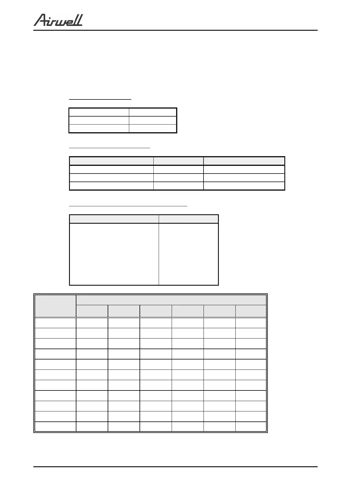
11.12 Jumper Setting
0 = Open Jumper (disconnect jumper).
1 = Close Jumper (connect jumper).
Self test Jumper – J1
OPERATION
J1
SELF-TEST
1
NORMAL
0
Compensation Jumper – J2
Model J2 (Default) Compensation
Wall Mounted 0 Activated
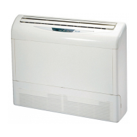
Floor/Ceiling 1 Deactivated
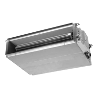
Ducted/cassette 1 Activated
Family selection Jumper – J3, J4 and J5
Family J5 J4 J3
Reserved
Reserved
Reserved
Wall Mounted (WNG/FLO)
Floor/Ceiling (PXD)
Reserved
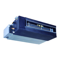
Ducted (LS)
Cassette (K)
0 0 0
0 0 1
0 1 0
0 1 1
1 0 0
1 0 1
1 1 0
1 1 1
IDU Model
Jumper Setting
J8 J7 J6 J5 J4 J3
FLO 9 0 0 0 0 1 1
FLO 12 0 1 0 0 1 1
FLO 18 0 0 1 0 0 0
FLO 28 0 0 1 0 0 1
SX 9 0 0 0 1 0 0
SX 12 0 1 0 1 0 0
SX 18 1 0 0 1 0 0
K 9 0 0 0 1 1 1
K 12 0 1 0 1 1 1
K 18 1 0 0 1 1 1
LS12 0 1 0 1 1 0
For wall mounted units Jumpers j7, j8 can be configured by service. All other jumpers on
the above table are factory default (cannot be changed by service).
For unit types as Cassettes, floor ceiling, and ducted, jumpers are set by a model plug.
 Loading...