3
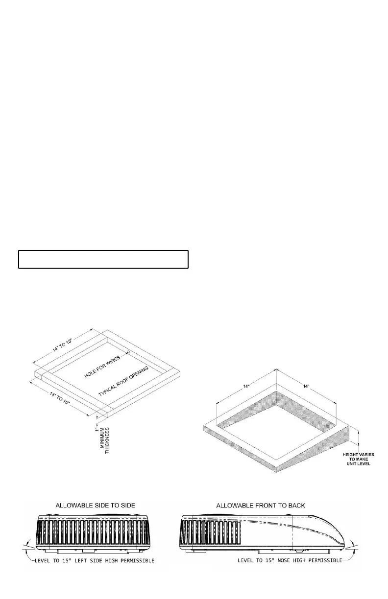
3. Examine the roof opening. If the opening is
smaller than 14” x 14”, the opening must be
enlarged. If the opening exceeds 15” x 15”, a
mounting frame must be field fabricated to reduce
the opening size (See Figure 1).
B. If a roof vent opening is not used, a new opening
(See Figure 1) will have to be cut into the vehicle
roof. A matching opening will also have to be cut
into the interior vehicle ceiling. If the ceiling opening
is carpeted, snagging could occur. After the
opening in the roof and interior ceiling are the
correct size, a framed support structure must be
provided between the exterior roof top and the
interior ceiling. The reinforced frame structure must
provide the following:
1. Capable of supporting both the weight of the roof
top heat pump and the interior ceiling assembly.
2. Capable of holding or supporting the roof outer
surface and interior ceiling apart, so that when the
roof top heat pump and ceiling assembly are
bolted together, no collapsing occurs.
Airxcel, Inc. requires that the spacing from the vehicle
roof top to the interior ceiling be no less than 1”. A
typical support frame is shown in Figure 1.
The frame must provide an opening through the frame
to allow passage for the power supply wiring. Route the
supply wiring through the frame at the same time the
support frame is being installed.
IMPORTANT – Allow 24” of supply wiring through
the support frame (working length).
After the support frame is installed, seal off all gaps
between the frame and both the roof exterior and the
interior ceiling of the vehicle (cavity walls). Additionally,
seal the gap around the electrical supply wiring.
C. The roof top heat pump must be mounted as
near level front to rear and side to side as possible
when the vehicle is parked level. Figure 3 shows
the maximum allowable degree deviations
mounting degrees from total surface flat plane).
If the roof of the vehicle is sloped such that the heat
pump cannot be mounted within the maximum
allowable degree deviations, an exterior leveling
shim will need to be added to make the roof top heat
pump level. A typical leveling shim is shown in
Figure 2.
Once the heat pump has been leveled, some
additional shimming may be required above the
interior ceiling assembly.
NOTE: The heat pump and interior ceiling assembly
must have a squared installation relationship before
they are secured together.
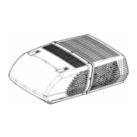
D. After the mounting hole is properly prepared, remove
the carton and shipping pads from the roof top heat
pump. Carefully lift the unit to the top of the vehicle.
Do not use the outer plastic shroud for lifting. Place
the roof top heat pump over the prepared mounting
hole. The sloped end (nose) of the shroud must face
towards the front of the vehicle. Pull the electrical
conduit down from the roof heat pump, through the
mounting opening and let hang.
E. Securing the roof top unit to the roof:
A mounting frame is supplied with the ceiling
assembly. Follow the steps below to secure the heat
pump to the roof. Refer to Figure 4.
1. On the Roof - Position the heat pump with the
basepan gasket over the 14” to 15” square
opening in the roof.
2. In the Coach - Install the ceiling assembly mount
frame using the four bolts found with the ceiling
assembly.
3. Proper tension has been achieved for each bolt
when any portion of each gasket indicating tab
has been pulled down even with the roof (See
Figure 4). The upper unit has now been properly
installed with optimum gasket compression.
 Loading...