DANGER – SHOCK HAZARD
MAKE SURE THAT ALL POWER SUPPLY TO
THE UNIT IS DISCONNECTED BEFORE
PERFORMING ANY WORK ON THE UNIT TO
AVOID THE POSSIBILITY OF SHOCK INJURY
OR DAMAGE TO THE EQUIPMENT.
DANGER! – WHEN USING NON-METALLIC
SHEATH CABLES (ROMEX, ETC.), STRIP
SHEATH BACK TO EXPOSE 4-6 INCHES OF
THE SUPPLY LEADS.
STRIP THE INDIVIDUAL WIRE LEAD ENDS
FOR WIRE CONNECTION (ABOUT 3/4" BARE
WIRE). INSERT THE SUPPLY WIRES INTO
THE ELECTRICAL CONNECTOR CLAMP.
SHEATH MUST PROTRUDE PAST THE
CLAMP BUSHING INSIDE THE BOX. MAKE
SURE SHEATH CABLE IS CENTERED IN
CLAMP BEFORE TIGHTENING CLAMP ON
SHEATH CABLE!!
DO NOT OVERTIGHTEN!! THIS COULD
RESULT IN PINCHING THROUGH THE
PLASTIC WIRE INSULATION AND CAUSE
SHORTING OR “HOT” WIRES TO GROUND
(SHOCK HAZARD). THE CLAMP IS
INTENDED FOR STRAIN RELIEF OF THE
WIRES. SLIGHT PRESSURE IS USUALLY
SUFFICIENT TO ACCOMPLISH THIS.
IF OTHER THAN NON-METALLIC CABLES
ARE USED FOR SUPPLY CONDUCTORS,
APPROPRIATE STRAIN RELIEF
CONNECTORS OR CLAMPS SHOULD BE
USED.
IN NO CASE SHOULD CLAMPING OR
PINCHING ACTION BE APPLIED TO THE
INDIVIDUAL SUPPLY LEADS (NEUTRAL
AND “HOT” WIRES).
DANGER – SHOCK HAZARD
TO PREVENT THE POSSIBILITY OF SHOCK
INJURY, THE WHITE WIRE MUST BE
CONNECTED TO NEUTRAL IN THE SERVICE
BOX ENTRANCE AND THE MECHANICAL
GROUND MUST BE CONNECTED TO A
GROUNDING LUG EITHER IN THE SERVICE
BOX OR THE MOTOR GENERATOR
COMPARTMENT.
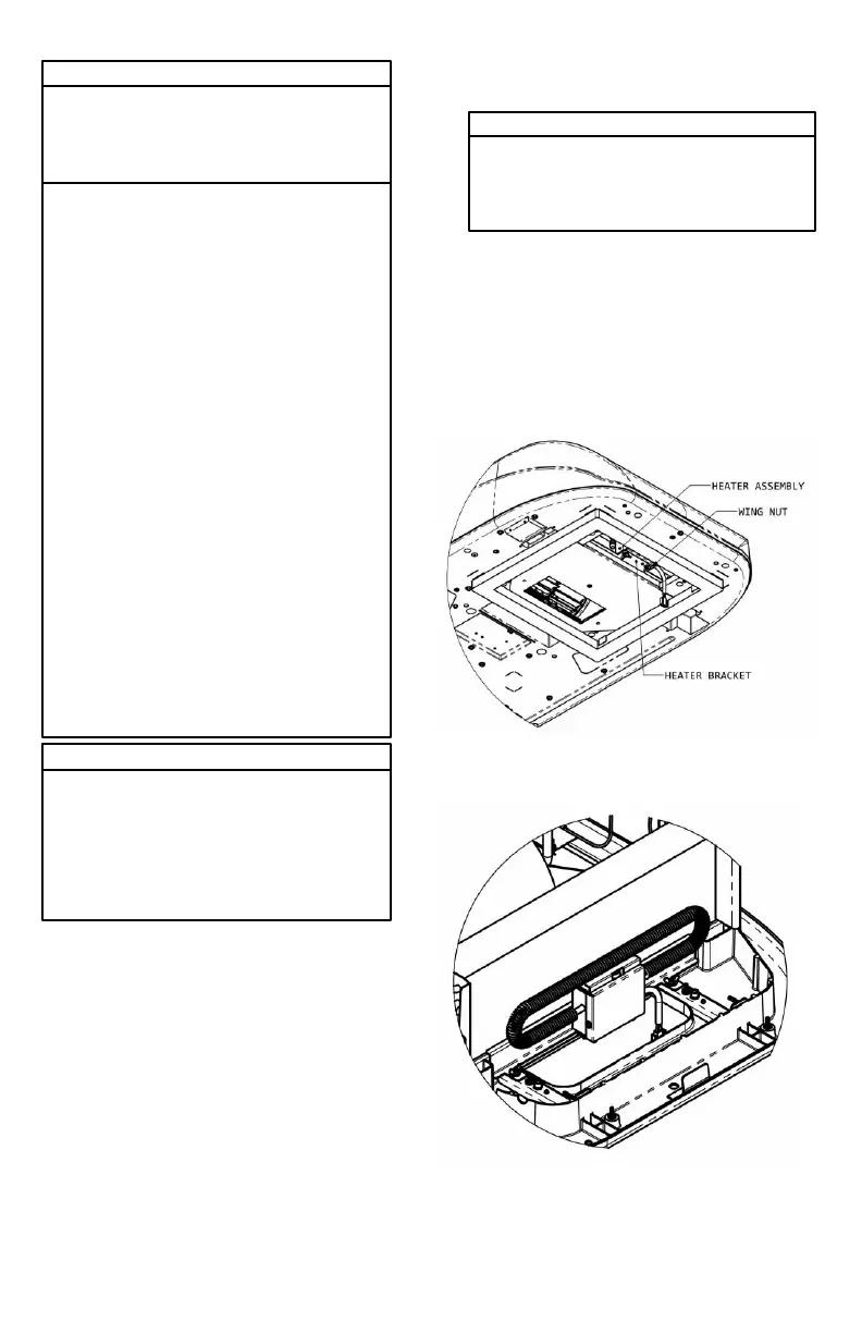
VI. INSTALLING THE OPTIONAL HEATER
ACCESSORY
IMPORTANT NOTE
The optional Heater Accessory is intended to
take the chill out of the indoor air when the air is
a few degrees too cool for comfort. The Heater
Accessory is an effective “chill chaser”. It is not
a substitute for a furnace.
If the heater option is being installed, mount the
heater bracket on the weld studs on the channels in
the return air opening as shown in Figure 5. Secure
the bracket using the wire nuts provided. The
heater is then assembled to the heater bracket,
lining up the weld studs on the heater with the holes
on the heater bracket. Secure the heater in place
using the wing nuts provided. (Replace the selector
switch control knob on the ceiling assembly with the
knob provided with the optional heater.
 Loading...