9
IX. OPERATION AND MAINTENANCE INSTRUCTIONS
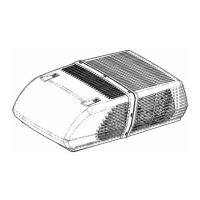
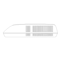
FOR 47000 SERIES
ROOF TOP HEAT PUMPS AND CEILING PLENUM
i. GENERAL INFORMATION
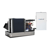
This roof mount heat pump is designed to operate from
a 115 VAC, 60 HZ, 1 Phase power supply. Any time a
heat pump is not operating properly, the power supply
should be examined by a qualified technician to verify
that the heat pump is receiving the proper power
supply.
The ability of the heat pump to maintain the desired
inside temperature depends on the heat gain or heat
loss of the recreational vehicle.
The size of the vehicle, amount of window area, amount
of insulation, direct exposure to the sun, outside
temperature and the number of people in the
recreational vehicle may increase the heat gain to such
an extent that the capacity of the heat pump is
exceeded.
As a general rule, air entering the heat pump will be
cooled about 15 to 20 degrees, depending on the
outside temperature and humidity conditions.
For example, if the air entering the return air grilles in
the heat pump is 80 degrees F., the air leaving the
discharge grilles in the heat pump will be 60 to 65
degrees F.
As long as this temperature difference is being
maintained between the return air and discharge air,
the heat pump is operating at its capacity. If the desired
inside temperature (normally 80 degrees F) cannot be
maintained, then the heat gain of the RV is too great for
the capacity of the heat pump.
Parking the vehicle in a shaded area, keeping windows
and doors shut and avoiding the use of heat producing
appliances in the vehicle will help to reduce the heat
gain. When possible, the addition of insulation and
tinted glass (especially in uninsulated vans) should be
considered.
NOTE: The optional Elect-A-Heat heating assembly is
intended to take the chill out of the indoor air when the
air is a few degrees too cool for comfort. The heating
assembly is an effective “chill chaser”. It is not a
substitute for a furnace.
R410A Roof Top Heat pumps
High Pressure Switch Lockout Circuit
Heat pumps and heat pumps using R410A refrigerant
may utilize a factory installed High Pressure Switch
Safety Circuit. In the event of an abnormal condition
(failure of fan motor, dirty condenser coil, dirty filters),
the high pressure switch will prevent the compressor
from continuing to run. Once the high pressure switch
has tripped, this safety circuit will “Lock Out” the
compressor preventing it from trying to restart or run
until the 115 VAC supply power has been turned off and
then back on to reset the High Pressure Switch Safety
Circuit. If repeated trips of the high pressure switch lock
out occur, then you must have the unit serviced by a
qualified technician.
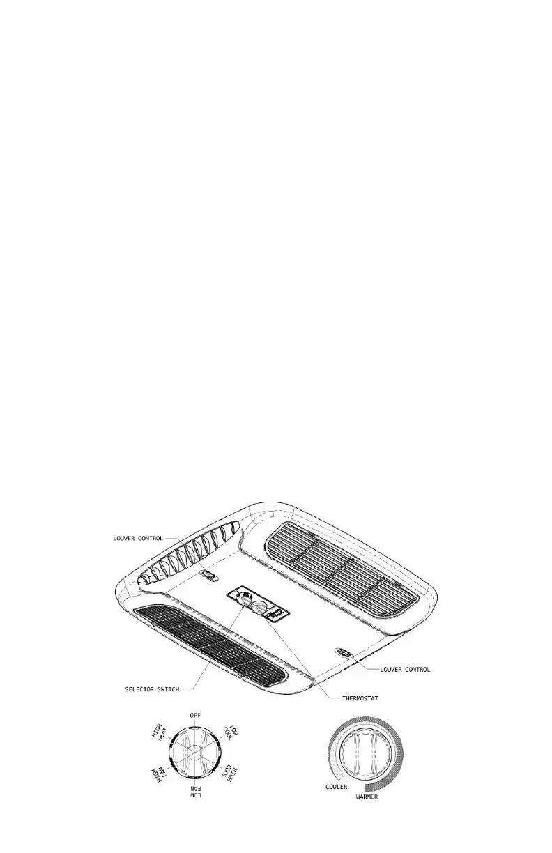
ii. CONTROL PANEL
If your RV heat pump is operated from the control
panel located in the ceiling assembly, there are
three controls on the ceiling assembly that help you
control the heat pump:
A. The Selector Switch – The selector switch
determines which mode of operation the heat
pump will be in. By rotating the selector switch,
the operator can obtain any system function
desired. System functions vary depending upon
options of both the roof top unit and ceiling
assembly. Figure 1 shows selector switch
location and lists all available functions by model.
The “Operation” section explains the operational
characteristics of each mode of operation.
 Loading...