59
• The clamp-on current meter is connected to the signal adapter by means of two non-
polarised wires (see Fig. 9).
• The signal adapter is also connected, by means of the 5-terminal connector, to the
System Control Unit, with two wires connected in parallel to the wires of the
Communications Gateway (see Fig. 9) and taking the power supply wires (red and black
labels) from connector 16 in Fig. 2.
4.4. Deflector, Security and Bypass Damper Assembly
For the installation and adjustment of the deflector, refer to the documentation supplied with
this manual.
The safety damper and the bypass damper are similar in terms of adjustment. However, their
locations are very different. The safety damper is designed for installations integrated by
means of the Communications Gateway, whereas the bypass damper is used when the
connection with the air conditioning unit is via IR or relays.
The location of the safety damper is at the output with the greatest air discharge velocity and
can be installed inside or outside of the duct.
The bypass damper must be installed before the first air discharge and as far as possible
from the air conditioning unit.
In both cases, they can be adjusted by moving the counterweight until the discharge velocity
is detected to be correct in all the zones and there are no noises in any of the outputs in the
rest of the installation.
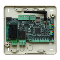
5. START-UP
5.1. System Control Unit Start-up
To start the Flexa System Control Unit, once it has been connected to the mains, take the
following steps:
1) The D11 mains LED (red) will light up. The motorised components will open, in groups of
3, lighting up the corresponding LEDs (M1 to M3, and then M4 to M6). The D2 channel
scanning LED (red) will then light up.
2) Wait for the D2 channel scanning LED (red) to turn off (approx. 3 minutes). Throughout
this period, if you have BlueFace or EnerFace in the installation, there will be a program
loading clock. Wait until it finishes.
3) After this time has passed, the D100 (green) Associating LED will start to flash, indicating
that the BlueFace or EnerFace can be configured (if present, EnerFace must be the first
to be configured) and the Flexa thermostats can now be associated.
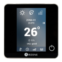
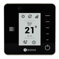
5.2. BlueFace/ EnerFace Start-up
BlueFace and EnerFace must be started up after the system has been connected to the
power supply and before associating any thermostats. To do this, follow these steps:
1) Wait for the loading screen to finish.
2) The recalibration screen will appear. Click on it if you want to recalibrate the screen (you
can do it later via the menu options) or wait until the damper selection screen appears.
The screen is calibrated by default.