To replace valves :—
After cleaning valve guide bores with
rag smear each valve stem with clean
oil and reverse procedure above.
IMPORTANT NOTE :—
If for any reason valve springs are re-
moved from their fixing block it is
important to see that upon replace-
ment the spring with narrow spaced
prongs is entered into the block from
the chamfered end.
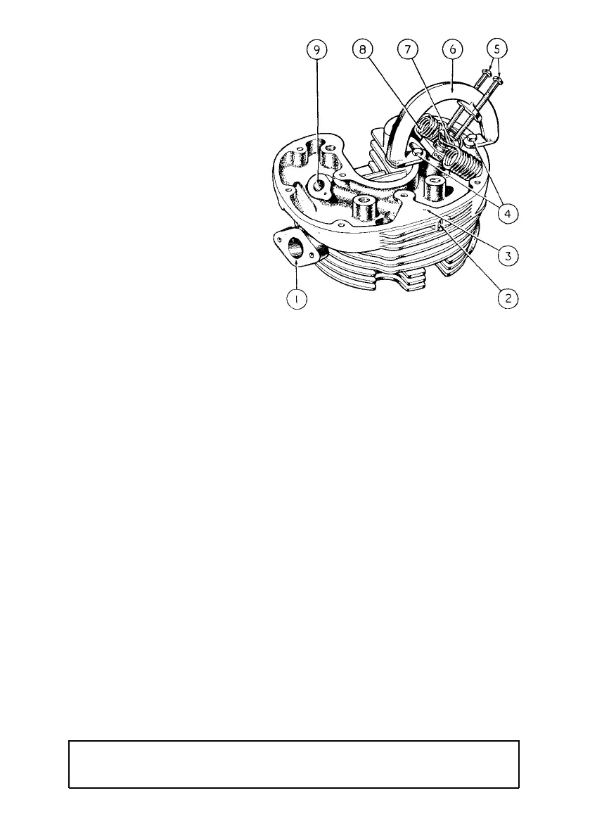
Illustration 9
Showing application of
valve spring compressor
1
2
3
4
INLET VALVE PORT.
ORIFICE FOR SCREW ADJUSTING OIL FEED
TO INLET VALVE.
OIL PASSAGE FROM ROCKER BOX TO
INLET VALVE GUIDE.
BOLTS, 010795 RETAINING V AL VE SPRI NG
COMPRESSO R TO CYLINDER HEAD.
5
6
7
8
9
BOLTS, IMPINGING ON V A LV E SPRING
CO LLA R WH IC H, UPON BEING SCREWED
DO W N , EXPOSE VA LV E C OL LE T THERE-
BY PERMITTING ITS REMOVAL.
BODY OF VA LV E SPRING COMPRESSOR.
COLLAR, RETAINING VALVE SPRINGS.
VALVE SPRINGS.
ORIFICE FOR VALVE GUIDE.
NOTE—The special valve spring compressor tool is not part of the standard tool kit but is
obtained from any of our dealers complete with bolts for attachment (Part
No. 014605.)
It is essential that the collets are correctly located on the valve stems. It will
be observed that the collet has two grooves machined in the bore and those
two grooves must register with the two rings on the valve stem. If fitted so that
only one of the grooves engages the ringed valve stem, damage will almost certainly
result.
On 350 c.c. the inlet valve head is larger in diameter than the exhaust. Therefore
inlet and exhaust valves are not interchangeable and no mistake can be made
when replacing same in the cylinder head.
On 500 c.c. both valve heads are identical in dimensions but are made of different
materials. Therefore, upon removal, valves should be laid aside so that they
may be identified for re-fitting. In case of doubt, see marking " In " or " Ex "
on top of stem above collet grooves.